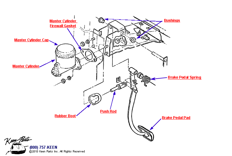
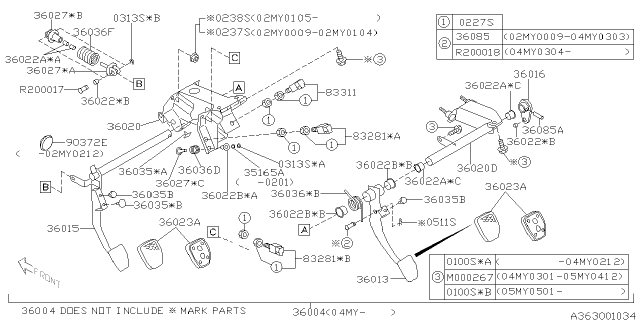
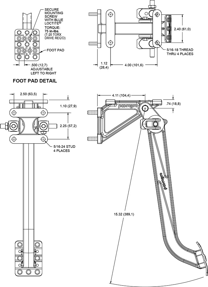
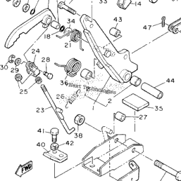
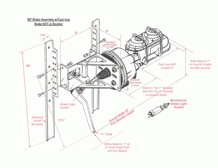
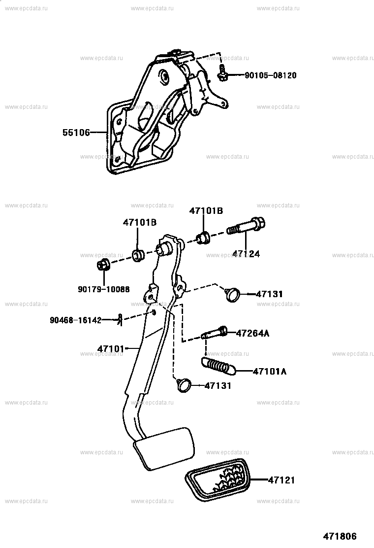
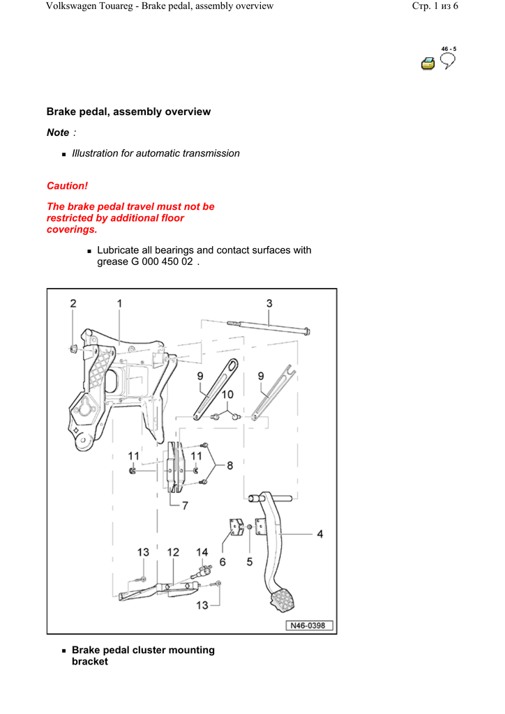
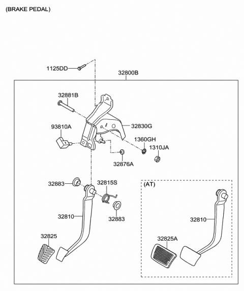
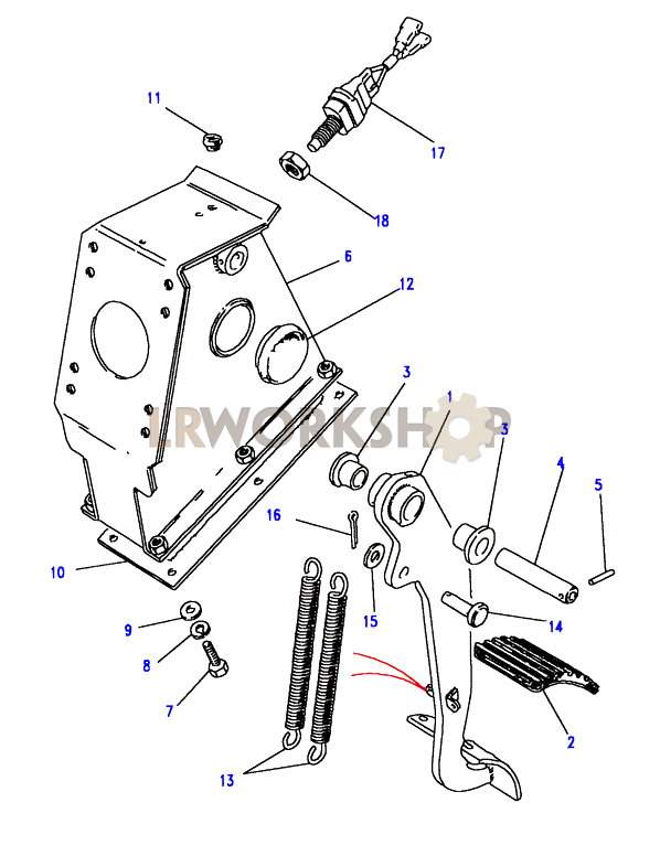
36 brake pedal assembly diagram
At Master Power Brakes, we are more than just disc brake conversion kits. Give us a call on all of your brake accessory needs and lean on our expert knowledge to walk you through your project and needs. May 17, 2021 · Brake Pedal Assembly. Brake Pedal Assembly. Brake Pedal Assembly. Item. Price. Qty Required. Diagram ID. 101187702 - HILL BRK LATCH KIT 9529<R. $33.28.
This replacement pedal assembly includes a .570 inch stock-size clutch shaft with Zerk fitting to lubricate both the clutch and brake pedals through the machined groove. All the parts for the accelerator pedal are sold seperately and are available in the "Additional Options:" tab above. Stock replacement pedal pads are available there as well.
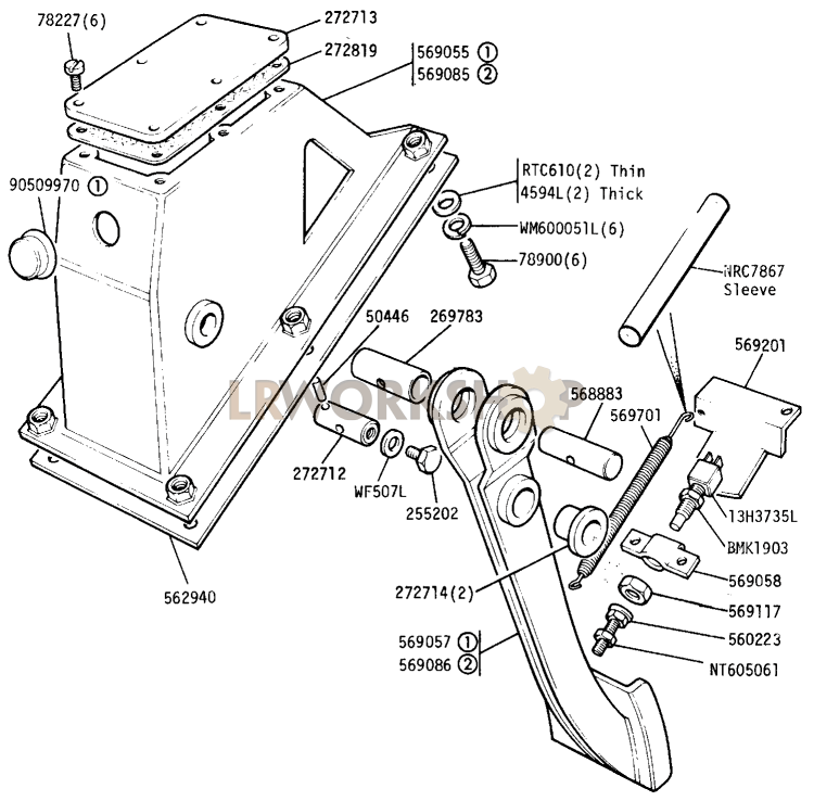
Brake pedal assembly diagram
Following are the main parts of an air brake: 1. Air compressor. It is used to build-up and maintain air pressure. The function of the air compressor is to build up and maintain air pressure required to operate air brakes and air-powered accessories. A compressor is designed to pump air into a reservoir which results in pressurized air. May 28, 2019 · Car Brake System Diagram. In this image, you will find power booster, master cylinder, ABS, caliper assembly, ABS hydraulic unit, hydraulic fluid lines, brake pedal, rotor in it. You may also find ABS system wiring, drum, parking brake cable, electronic ABS controller, car brake system, brake system of car, car, car internal structure in this ... This diagram shows an exploded view of the pedal cluster assembly. Different year cars may have slightly different configurations, but the general design and assembly is the same for all the 911s. This diagram shows the pedal cluster assembly for 911s 1974 and later.
Brake pedal assembly diagram. Start your holidays early, HUGE SAVINGS & HOLIDAY DEALS have already begun! 2022 Kawasaki KLX230R Brake Pedal assembly detail & product fiche. Shop original factory replacement parts at RevZilla today! 2019-07-08 · In the classic mechanical brake system, there was a cable which connected the brake pedal and brake shoe assembly together. When the driver stepped on the brake pedal, it pulled on the cable and allowed the brake drum spinning to slow down. Clutch/Brake Pedal assembly, OEM. The clutch/brake pedal assembly on my 1996 Ford F150 has worn out. I have found several online that are available, one is from Amazon. But I can not determine that the part they have for sale is the correct part number for my truck. Amazon has an F3TZ2455-A in stock but says it is for an F250 & F350. In the classic mechanical brake system, there was a cable which connected the brake pedal and brake shoe assembly together. When the driver stepped on the brake pedal, it pulled on the cable and allowed the brake drum spinning to slow down. This was used on cars in the early 20th century, and is still used on bikes today.
Brakes General Your EZGO cart is fitted with a mechanically initiated rear drum brake system. The braking systems contains a service brake and park brake pedal, release linkage for park brake, compensator system, equalizer link, braking cables and wheel brake systems that self adjust. Brake Pedal and Linkage Inspection 1. Inspection of brake pedal return bumper. Park Brake Pedal Pad. 70256G01. Fits 1994-Current E-Z-GO TXT and Medalist Electric and Gas Vehicles. Learn More. Add to Cart. $58.10. Park Brake Pedal Assembly. 641766. Used on 1996-2001 E-Z-GO Gas & Electric Industrial & Utility Vehicles with or without brake lights. Step 2:Test-fit the original brake pedal axle into the new Lokar small amount of free play at the brake pedal pad. brake pedal before attempting installation. Due to manufacturing tolerances and possible differences between OE and replacement parts, some brake pedal axles may be too tight. If the brake pedal axle does not washers and nylock nuts. Torque these to 18-24 ft. lbs. Assemble the brake pedal on to the brake pedal frame mount. Install the clevis on to the brake pedal and adjust the pedal location so the center of the clevis pin is ½" forward from the center line of the brake pedal pivot. 3. The push rod can now be cut to the correct length.
TRANSMISSION, BRAKE AND TRACTION PEDAL ASSEMBLY diagram and repair parts lookup for Toro 13AL60RG044 (LX 426) - Toro Lawn Tractor (SN: 1L107H10100 & Above) (2008) Order Status Customer Support 512-288-4355 My Account. Login to your PartsTree.com to view your saved list of equipment. This is the how to of installing our under the floor brake pedal assembly! This diagram shows an exploded view of the pedal cluster assembly. Different year cars may have slightly different configurations, but the general design and assembly is the same for all the 911s. This diagram shows the pedal cluster assembly for 911s 1974 and later. May 28, 2019 · Car Brake System Diagram. In this image, you will find power booster, master cylinder, ABS, caliper assembly, ABS hydraulic unit, hydraulic fluid lines, brake pedal, rotor in it. You may also find ABS system wiring, drum, parking brake cable, electronic ABS controller, car brake system, brake system of car, car, car internal structure in this ...
Following are the main parts of an air brake: 1. Air compressor. It is used to build-up and maintain air pressure. The function of the air compressor is to build up and maintain air pressure required to operate air brakes and air-powered accessories. A compressor is designed to pump air into a reservoir which results in pressurized air.







0 Response to "36 brake pedal assembly diagram"
Post a Comment