34 free body diagram torque
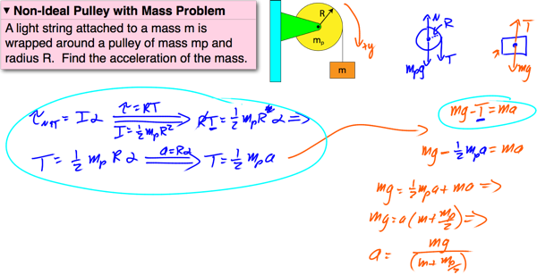
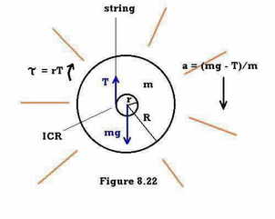
Figure 17.26 (a) Force-torque diagram on rotor and (b) free-body force diagram on hanging object. While the hanger is falling, the rotor-washer combination has a net torque due to the tension in the string and the frictional torque, and using the rotational equation of motion, \[\operatorname{Tr}-\tau_{f}=I_{R} \alpha_{1}\] Provide a free body diagram and all necessary bending moments and torque diagrams. 2. Calculate the dimensions of the keys and the key ways at shaft 1 and 2 for the two gears and the pulleys. 3. Determine the critical speed of rotating shaf t 2. B. DRAWINGS AND ASSEMBLY 1. Make the construction drawings of all different parts (2D) 2.
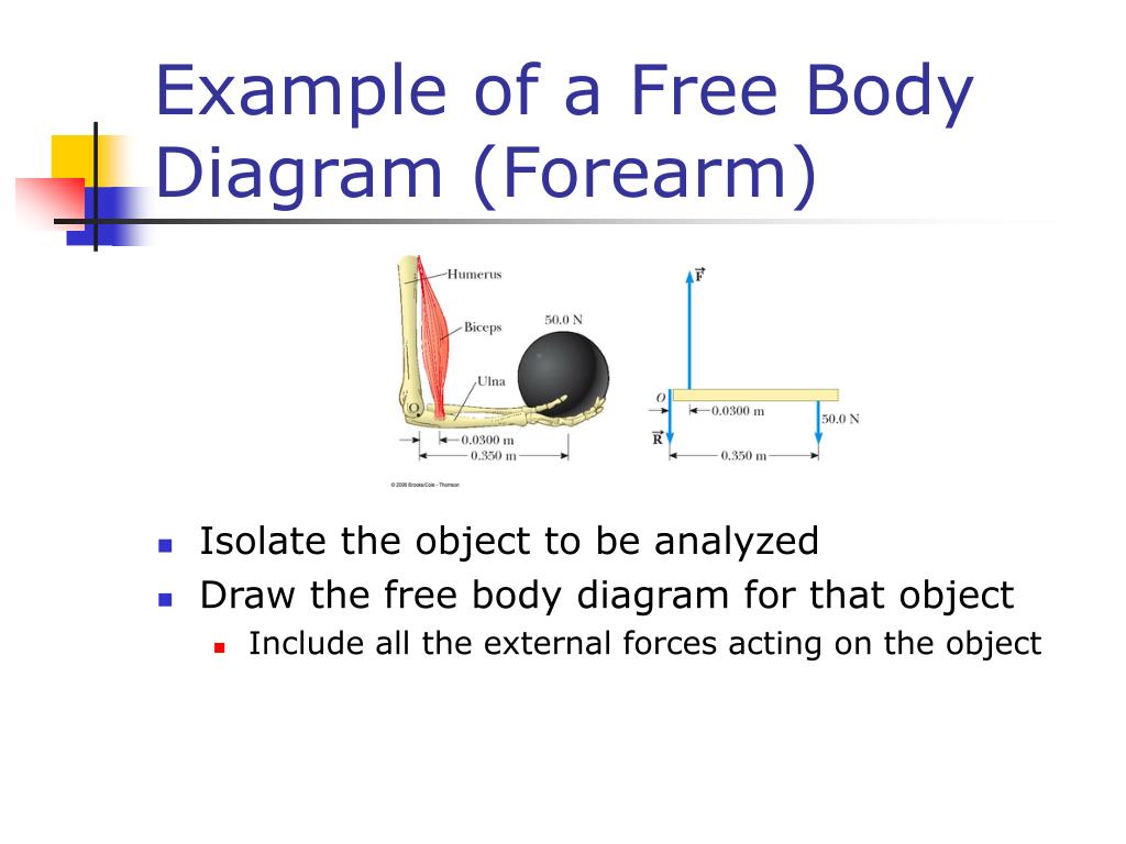
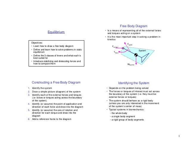
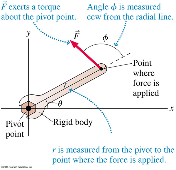
For solving for net torque, an accurate free body diagram is critical. Step 1: Draw the FBD and include a coordinate axes. Label the axis of rotation. Step 2: Draw all of the forces that are acting on the body, using the information given to accurately place the forces relative to the axis of rotation.
Free body diagram torque
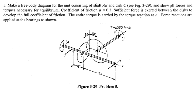
CALCULATIONS 1. Calculate the smallest safe shaft diameter for the shaft 1 and 2. Provide a free body diagram and all necessary bending moments and torque diagrams. 2. Calculate the dimensions of the keys and the keyways at shaft 1 and 2 for the two gears and the pulleys. 3. Determine the critical speed of […] As a result, the AERS has no differential braking or torque vectoring function. As such, it is not necessary to separate the left and right wheels in a vehicle model. For this reason, the AERS is modeled with a bicycle model in this paper. Figure 4 shows the free-body diagram of the bicycle model for the AERS [9,25,26]. I'm trying to study the free body diagram of this differential-drive mobile robot in case of straight trajectory (same torque applied on both of rear wheels) and pure rolling motion I started studying the whole system, in which i have the inertial force, vertical force (weight), two friction force Ft for the rear wheels and a friction force Fta ...
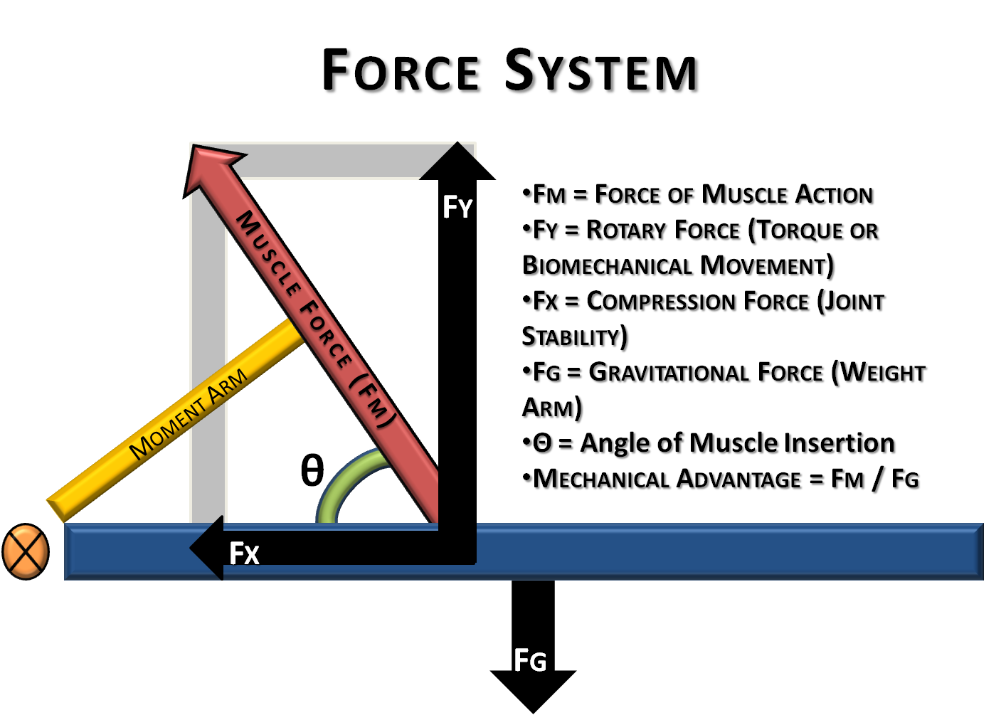
Free body diagram torque. It is required to determine the forces in the links and the torque T 2. The free body diagrams are shown in Fig.11.9(b). Link 3: Link 3 is a three-force member, F 23, F 43, and Q. Let F 43 be broken into its normal and tangential components and , respectively. The normal component is along the link 3 and tangential component is perpendicular to ... The maximum torque is required when the center of gravity of the rotating body is the position at which the moment caused by gravity is the maximum, and the direction of driving acceleration is opposite to the moment caused by gravity. A free body diagram (FBD) of such a movement in the case of the shoulder joint is shown in Figure 4. Based on ... Provide a free body diagram and all necessary bending moments and torque diagrams. 2. Calculate the dimensions of the keys and the key ways at shaft 1 and 2 for the two gears and the pulleys. 3. Determine the critical speed of rotating shaf t 2. B. DRAWINGS AND ASSEMBLY 1. Make the construction drawings of all different parts (2D) 2. Above is a free-body diagram showing all the forces exerted on the forearm bar. According to the Laws of Statics (i.e., Newton's First Law and the lever rule), the net force on the stationary bar must be zero, and the net torque on the bar must also be zero. The "hand" end of the bar can be moved up...
1. Let's say you are riding a bike very fast, and then you sharply turn into a slide (where the bike is sliding perfectly sideways). I'm trying to calculate the angle that the bike would be leaning at, but I'm having trouble creating the free body diagram. Right now I have the normal force and friction force drawn where the wheels touch the ... Mechanical Engineering: Engineering mechanics - statics What you'll learn Equilibrium of a particle and of a body Reactions of surfaces and of supports Free body diagram Position, velocity and acceleration Newton's laws Working with forces Torque Mechanics Engineering mechanics mechanical engineering engineering statics Figure \(\PageIndex{2}\): (a) In the case of the wheelbarrow, the output force or load is between the pivot and the input force. The pivot is the wheel's axle. Here, the output force is greater than the input force. Thus, a wheelbarrow enables you to lift much heavier loads than you could with your body alone. Drawing the free body diagram for the pendulum bob lets us write an expression for the net force acting on it. Define these variables: \( T = \) tension in the rod ... We learn from a physics text book that "The torque acting on the particle with respect to the origin O is defined in terms of the vector (cross) product of r and F as"
Calculate the smallest safe shaft diameter for the shaft 1 and 2. Provide a free body diagram and all necessary bending moments and torque diagrams. Evaluate the proposed product from the engineering point of view. Explain what extent are intangible cultures worth maintaining? To what extent are intangible cultures worth maintaining? The free-body force diagram on the pendulum is also shown in Figure 24.7b. In particular, there is an unknown pivot force, the gravitational force acting at the center of mass of the rod, and the gravitational force acting at the center of mass of the disk. The torque about the pivot point is given by (OBQ09.172) Figure A represents a free body diagram of the hip of a patient standing on the right leg. The forces and distances are labeled on the diagram and the resulting hip joint force (J) = 1800N. What is the resultant value for J when the acetabular component is medialized given the new distances shown in Figure B? I first created the following diagram (after watching some videos, I had initially combined masses and this is wrong). ##F_p## Is the gravitational force of the board on the boat. ##N_0## Is the corresponding normal force the board experiences from the boat. ##F_m## Is the force of me at the...
Free-body diagrams of the isolated component parts of the tripod landing gear, together with the notation for unknown reactions and internal forces and .... Solution for C44. Draw the free-body diagram of the wheel and member ABC used as part of the landing gear on a jet plane. The hydraulic cylinder AD acts as ....

We consider the torque from friction of the pendulum to be a vector perpendicular to the plane where the pendulum and cart move. That is, the torque is in the direction of the unit vector k which extends out of the plane. The magnitude of the torque is given by −b θ' where θ' is the angular velocity. We can regard the force from the torque as being equivalent to a force applied at the end ...

11.4 Problem solving. The process for solving problems with torque is nearly identical to the process for solving problems with force (see section 9.4).However, instead of a free body diagram—which represents the system as a single point—we'll use an extended free body diagram (E-FBD); with torque, the location where the force is applied is important.

Taking the moment about point C of the free-body diagram suggests the following: Free-body diagram of segment AC. The horizontal thrust at both supports of the arch are the same, and they can be computed by considering the free body diagram in Figure 6.5c. Taking the moment about point C of the free-body diagram suggests the following: Free ...

For T₂, its free-body diagram shows us it is only responsible for the mass of m₂, we can say that T₂ = a * m₂. With that said, T₂ = (2.4 m/s²) * (2 kg) = 4.8 N . On the other hand, T₁ is the tension force that pulls both the weight of m₁ and m₂.
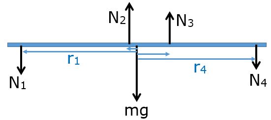
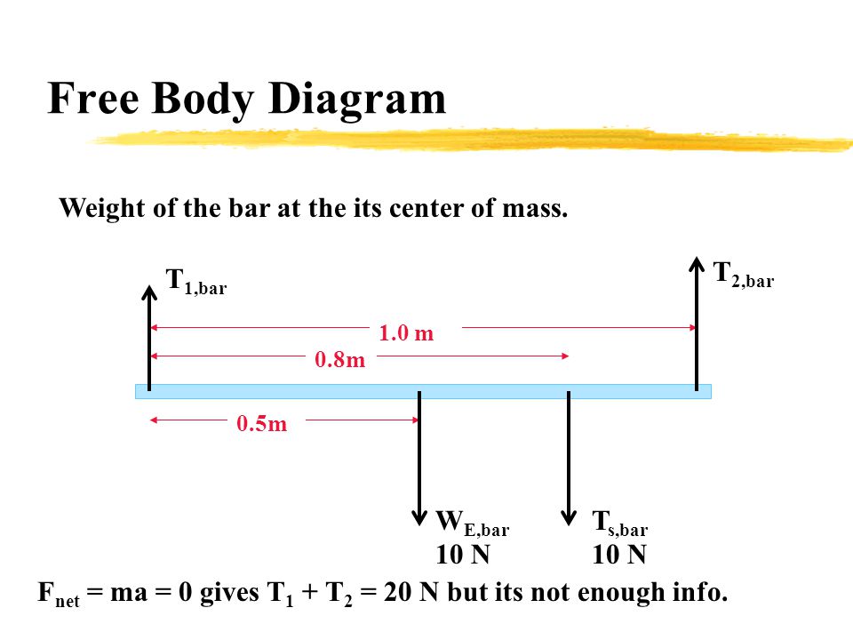
Apply static equilibrium conditions to the system. That is net torque acts on the system is zero. (a) The boy, weight 600N, walks toward the right with a distance x from point A. The free-body diagram is shown below.
I'm trying to study the free body diagram of this differential-drive mobile robot: So i started considering just a straight motion (torque on the right wheel is equal to the torque on the left wheel) and i wrote down the equilibrium equations about forces and torques.

I'm trying to study the free body diagram of this differential-drive mobile robot in case of straight trajectory (same torque applied on both of rear wheels) and pure rolling motion I started studying the whole system, in which i have the inertial force, vertical force (weight), two friction force Ft for the rear wheels and a friction force Fta ...
As a result, the AERS has no differential braking or torque vectoring function. As such, it is not necessary to separate the left and right wheels in a vehicle model. For this reason, the AERS is modeled with a bicycle model in this paper. Figure 4 shows the free-body diagram of the bicycle model for the AERS [9,25,26].

CALCULATIONS 1. Calculate the smallest safe shaft diameter for the shaft 1 and 2. Provide a free body diagram and all necessary bending moments and torque diagrams. 2. Calculate the dimensions of the keys and the keyways at shaft 1 and 2 for the two gears and the pulleys. 3. Determine the critical speed of […]


0 Response to "34 free body diagram torque"
Post a Comment