38 stepper motor circuit diagram
The circuits for two-wire stepping are as follows: Unipolar stepper two-wire circuit: Biolar stepper two-wire circuit: Programming the Microcontroller to Control a Stepper. Because both unipolar and bipolar stepper motors are controlled by the same stepping sequence, we can use the same microcontroller code to control either one. Any stepper motor can be used as a generator. In contrast to other generators, a stepper motor produces a large induced voltage even at low rotational speeds. The type used here, with a DC resistance of 2×60 Ω per winding, can generate more than 20 V when turned by hand, without any gearing. The circuit diagram for a 'hand-cranked torch ...
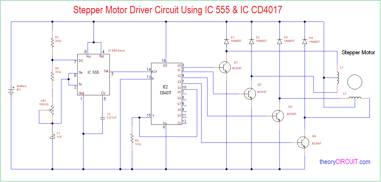
Stepper Motor Driver Circuit Diagram and Explanation. The figure shows the circuit diagram of two stage stepper motor driver. Now as shown in the circuit diagram the 555 circuit here is to generate clock or the square wave. The frequency of clock generation in this case cannot be kept constant so we need to get variable speed for the stepper motor.

Stepper motor circuit diagram
Circuit diagram: Stepper Motor Controller Circuit Diagram. IC3, IC4 and IC5 are all of this type (which is economically priced). Here IC3 and IC4 are wired as comparators. Their non-inverting inputs are driven by the previously mentioned I and Q signals, with the inverting inputs set to a potential equal to half the supply voltage. A Stepper Motor rotates precisely by synchronising the pulse signals from a controller, which are given through a Driver. A Stepper Motor Driver ...Jul 4, 2017 · Uploaded by Electronics HubIntroduction · Components Required · Component Description · Circuit Design Stepper Motor Wiring Diagram – arduino stepper motor wiring diagram, cnc stepper motor wiring diagram, leadshine stepper motor wiring diagram, Every electrical structure is composed of various distinct pieces. Each component should be set and connected with different parts in particular manner. If not, the structure won’t function as it should be.
Stepper motor circuit diagram. A stepper motor or a step motor is a brushless, synchronous motor which divides a full rotation into a number of steps. Unlike a brushless DC motor which rotates continuously when a fixed DC voltage is applied to it, a step motor rotates in discrete step angles.The stepper motor can be controlled with or without feedback. Stepper motors work on the principle of electromagnetism. There is a ... The following diagram shows the connections to be made for an 8-wire series connected bipolar stepper motor. The next diagram shows the connections for an 8-wire parallel connected bipolar stepper motor. It is not realistic to sort out all of the possible combinations of connections with an ohmmeter or by feel. You need the datasheet for the ... Jul 19, 2019 · Stepper Motor Controller Schematic Circuit Diagram. Admin July 19, 2019. 0 138 3 minutes read. Stepper motors are available in several versions and sizes with a variety of operating voltages. The advantage of this general-purpose controller is that is can be used with a wide range of operating voltages, from approximately 5 V to 18 V. Feb 26, 2008 — Its inputs control the speed and direction of the motor. The diagram below shows the typical setup of the circuit. The A and B outputs would ...
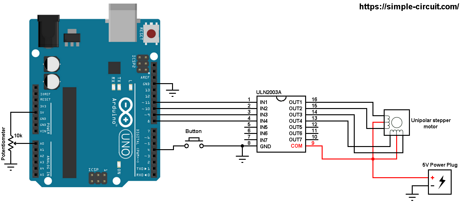
The wiring diagram/schematic below shows you how to connect the ULN2003 driver board to the 28BYJ-48 stepper motor and the Arduino. The connections are also given in the table below. Wiring diagram for ULN2003 driver with 28BYJ-48 stepper motor and Arduino. I used a breadboard and some jumper wires to connect the driver board to an external ... The UC3717A is characterized for operation over the temperature range of 0°C to +70°C. UC3717A. BLOCK DIAGRAM. FEATURES. DESCRIPTION. Voltage. Logic Supply, VCC ... Current limit wiring diagram for A4988 driver. To measure the reference voltage, the driver needs to be powered. The A4988 only needs power via VDD (5V) and you need to connect RST and SLP together, otherwise the driver won't turn on. It's best to disconnect the stepper motor while you do this. There are many variations in stepper motor wiring. For our purposes, we will focus on steppers that can be driven with commonly available drivers. These are Permanent Magnet or Hybrid steppers wired as 2-phase bipolar, or 4-phase unipolar. ©Adafruit Industries Page 9 of 21.
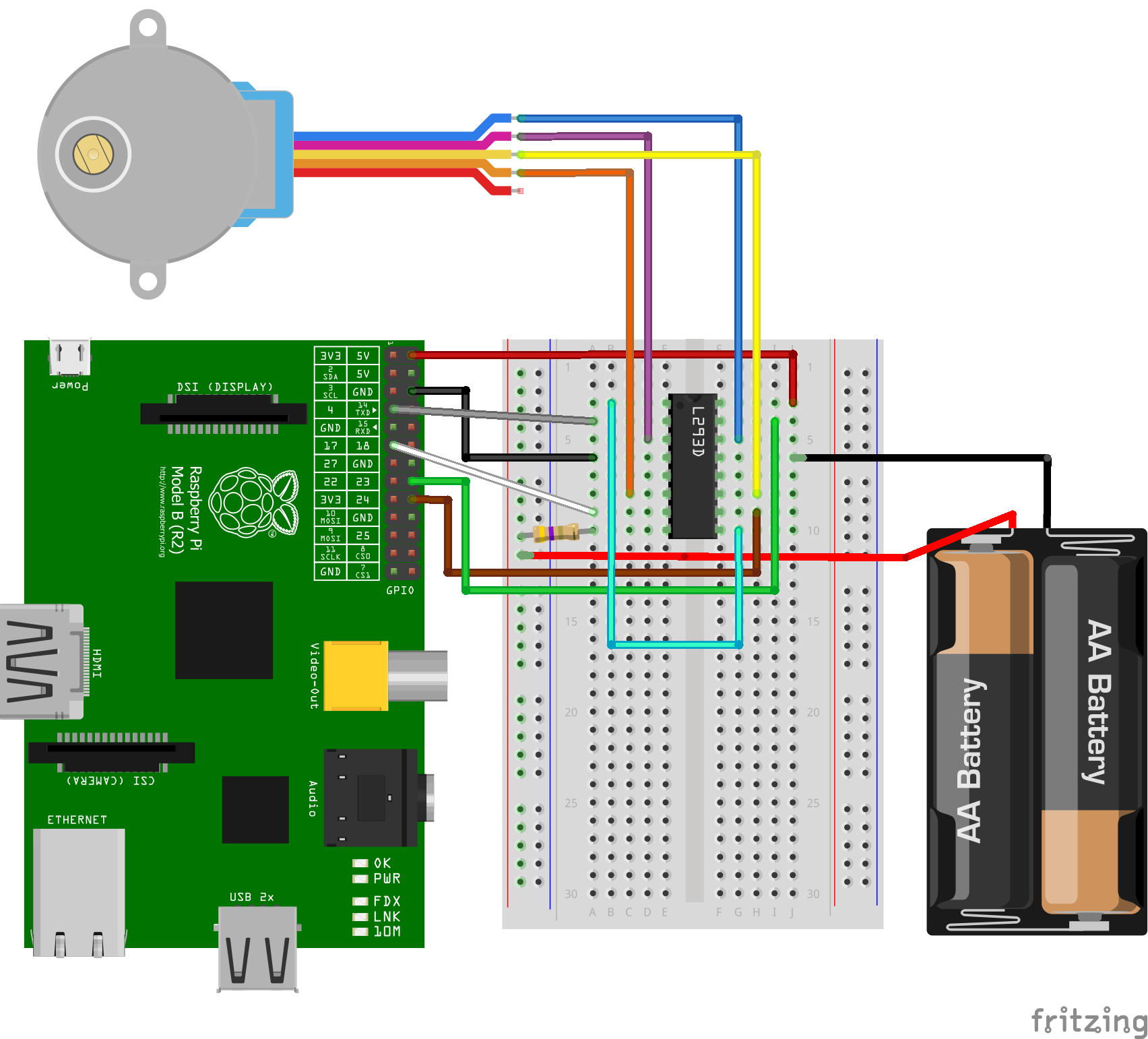
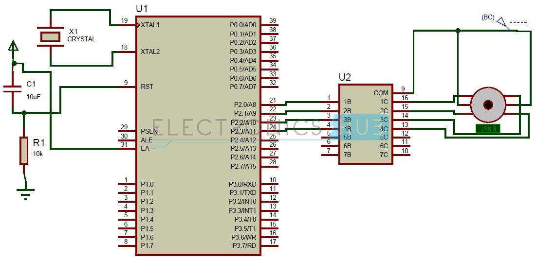
Circuit diagram of stepper motor interfacing with pic16f877a microcontroller is given below: The easiest way of interfacing a stepper motor with a microcontroller is via ULN2003 transistor array chip. This IC has seven Darlington transistor drivers and is used for high current torque motors. In the circuit diagram, the four input pins (1B, 2B ... Longs Stepper Motor Wiring Diagram. Effectively read a electrical wiring diagram, one offers to know how the particular components in the program operate. For instance , if a module is usually powered up also it sends out a signal of fifty percent the voltage plus the technician would not know this, he would think he offers a challenge, as he ... Dedicated integrated circuits have dramatically simplified stepper motor driving. To apply these ICs, designers need little specific knowledge of motor driving techniques, but an understanding of the basics helps in finding the best solution. This note explains the basics of stepper motor driving and describes the drive techniques used today. Ethernet Smooth stepper control 22kw Water cooled spindle. Subscribe and get alert about your Wishlist. Db25 Connector Microstar Laboratories Knowledge Base Knowledge Laboratory Connector If this is your first visit be sure to check out the FAQ by clicking the link above. Leadshine stepper motor wiring diagram. More than a year-and-a-half into the COVID-19 pandemic […]
Image from page 578 of "Machinery for metalliferous mines : a practical treatise for mining engineers, metallurgists and managers of mines" (1902)
Nema 17 Stepper Motor Circuit. Controlling nema 17 stepper motor with datasheet wiring control l298n a4988 driver arduino pololu and nema17 23 specs kit 17hs4023 drive a the. Controlling Nema 17 Stepper Motor With Arduino And A4988 Driver Module. Drive A Nema 17 Stepper Motor With The Rpimotorlib Python Library For A4988 Diy Projects.
MSP430 STEPPER MOTOR DRIVER FOR WINDOWS 8
Jan 24, 2018 - Explore Sarfaraz Ahmad's board "Circuit diagram" on Pinterest. See more ideas about circuit diagram, cnc, stepper motor.
Stepper motor controller - Driver circuit with circuit design
STEPPER MOTOR CONTROL CIRCUITS •The controller decides on the number and direction of steps to be taken (based on the application). The pulse sequence generator translates the controller's requests into specific stepper motor coil voltages. •The driver amplifiers boost the power of the coil drive signals.
555 Timer Stepper Motor Controller Circuit
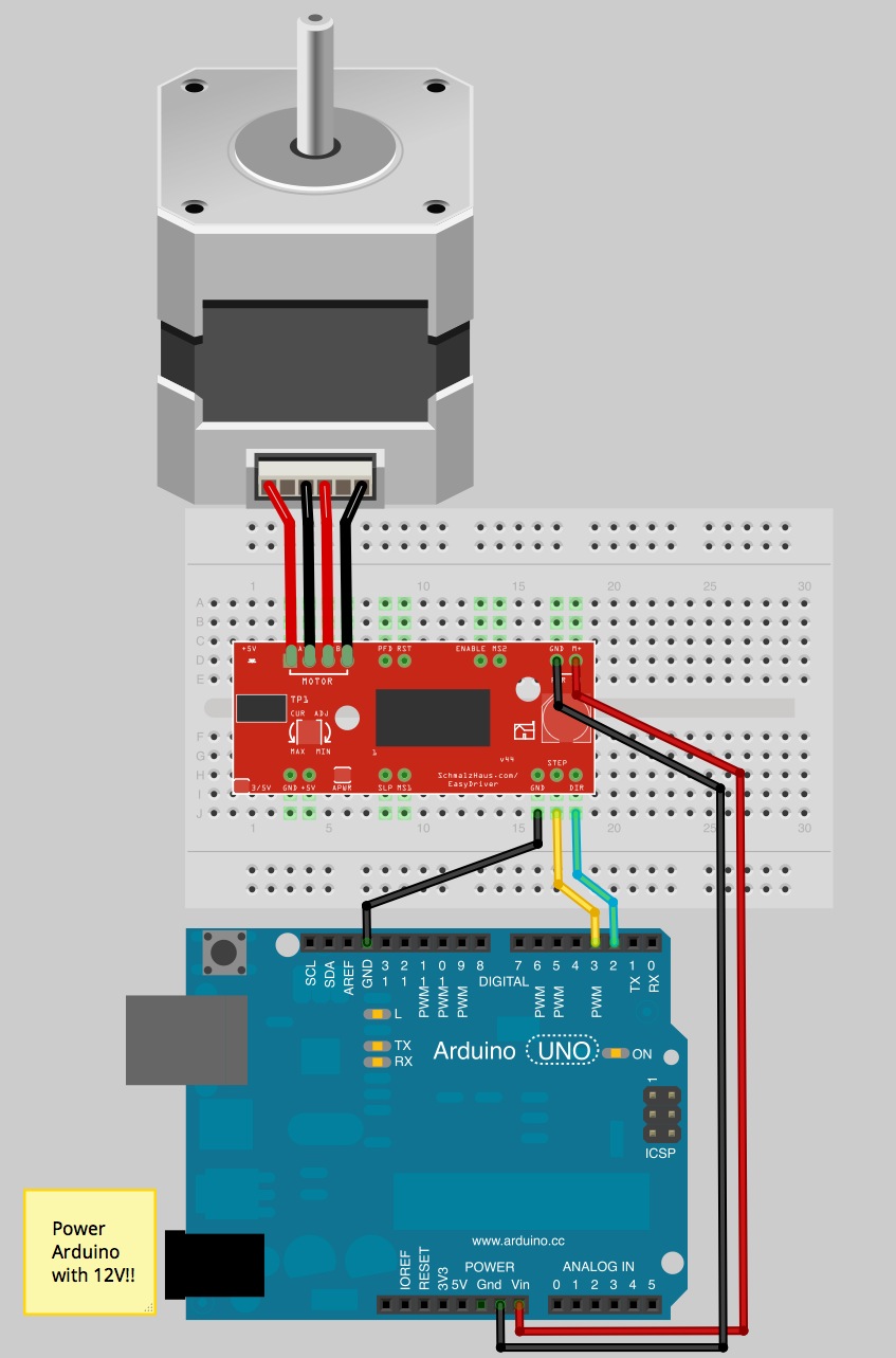
Made with Fritzing. How the stepper motor works. The stepper motor has two coils to control it as shown in Figure 14. Each coil has a center connection as well, and the center connections are joined together, which is what makes this a unipolar stepper.If you don't connect the center connection, then the motor will work very much like a bipolar stepper, each coil operating independently.

Stepper Motor Generator Schematic Circuit Diagram
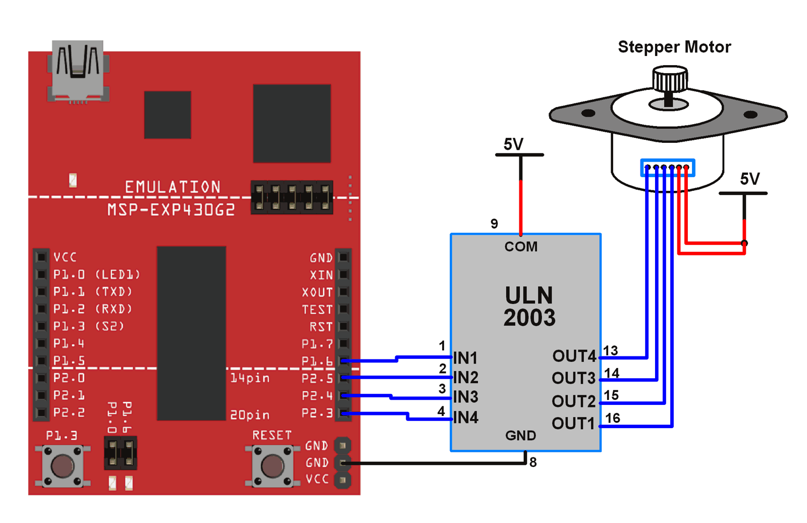
Step 7: Connect the outputs of the ULN2003a to the 4 wires of the stepper motor as shown in the circuit diagram below. Note: Please note that while connecting the pins 1C, 2C, 3C, and 4C to the wires of the stepper, try all the possible connections. If the motor starts oscillating instead of rotating, then carefully look for the 4 coil wires ...

Image from page 1081 of "The Street railway journal" (1884)
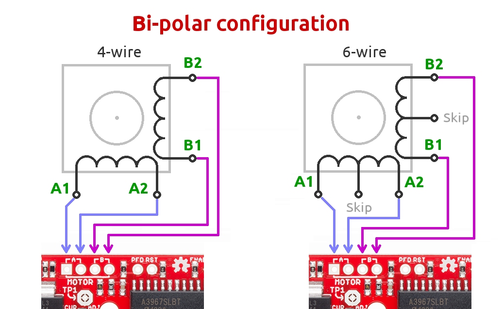
Stepper motor wiring diagrams . The 4-wire motor can only be driven by bipolar waveforms. The 6-wire motor, the most common arrangement, is intended for unipolar drive because of the center taps. Though, it may be driven by bipolar waves if the center taps are ignored.
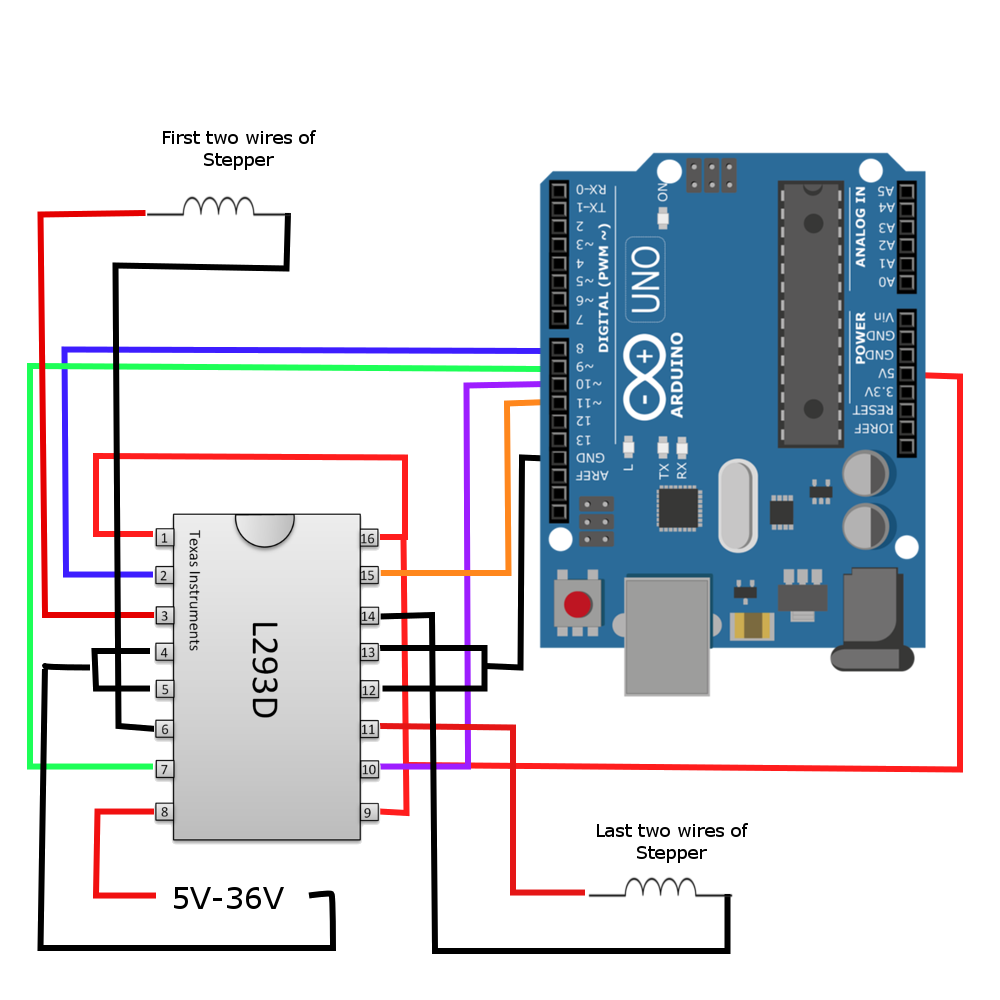
Driving Any Stepper Motor for Less Than $1 with The L293 ...
Circuit Diagram of Curtain Opener and Closer - ElectronicsHub.Org. Components used in this Circuit: IC; IC1 (CD4013) IC2 (ULN2003) Resistor; R1-R4 (5.6k) R6, R5 (1K) C1 (. 1uf) Stepper Motor; Description: This circuit is made up of two ICs named CD4013 and ULN2003 with few more easily available components.

Maximite Stepper Motor Interface Circuit Diagram | Super ...
Easy to Build CNC Mill Stepper Motor and Driver Circuits: This is a follow up to the Easy to Build Desk Top 3 Axis CNC Milling Machine Once you get the machine all put together its time to make it go. So it's time to drive the motors. And here I've put together a circuit that I think is the absolu…
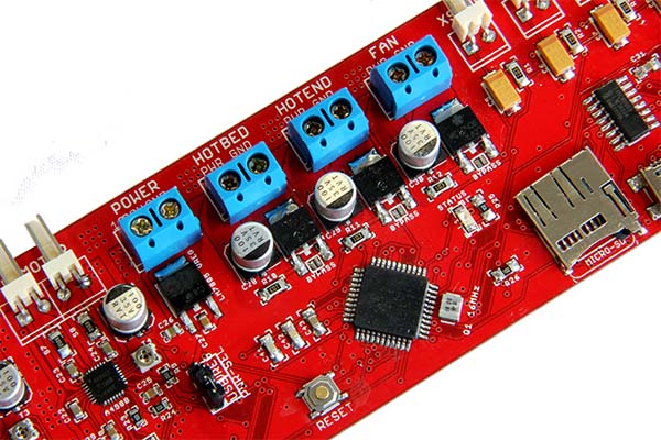
Melzi - Geeetech Wiki
Stepper motor control circuit is a simple and low-cost circuit, mainly used in low power applications. The circuit is shown in the figure, which consists of 555 timers IC as a stable multi-vibrator. The circuit is shown in the figure, which consists of 555 timers IC as a stable multi-vibrator.
What is the diagram of a stepper motor? - Quora
Referring to the schematic diagram, two IC’s U1A,B and U2A,B,C,D form the oscillator, and forward-reverse quadrature signals needed to drive the stepper motor M1. Specifically, XOR gate U2A, wired as an inverter, and U2B wired as a buffer, form an oscillator circuit with R1, C1 and R8.

Image from page 1085 of "Electric railway journal" (1908)
Or you are a student, or maybe even you who just would like to know concerning Stepper Motor Circuit Diagram. Interfacing Stepper Motor With 8051 Using Keil C – At89C51, size: 800 x 600 px, source: electrosome.com. Whatever you are, we try to bring the web content that matches exactly what you are trying to find.
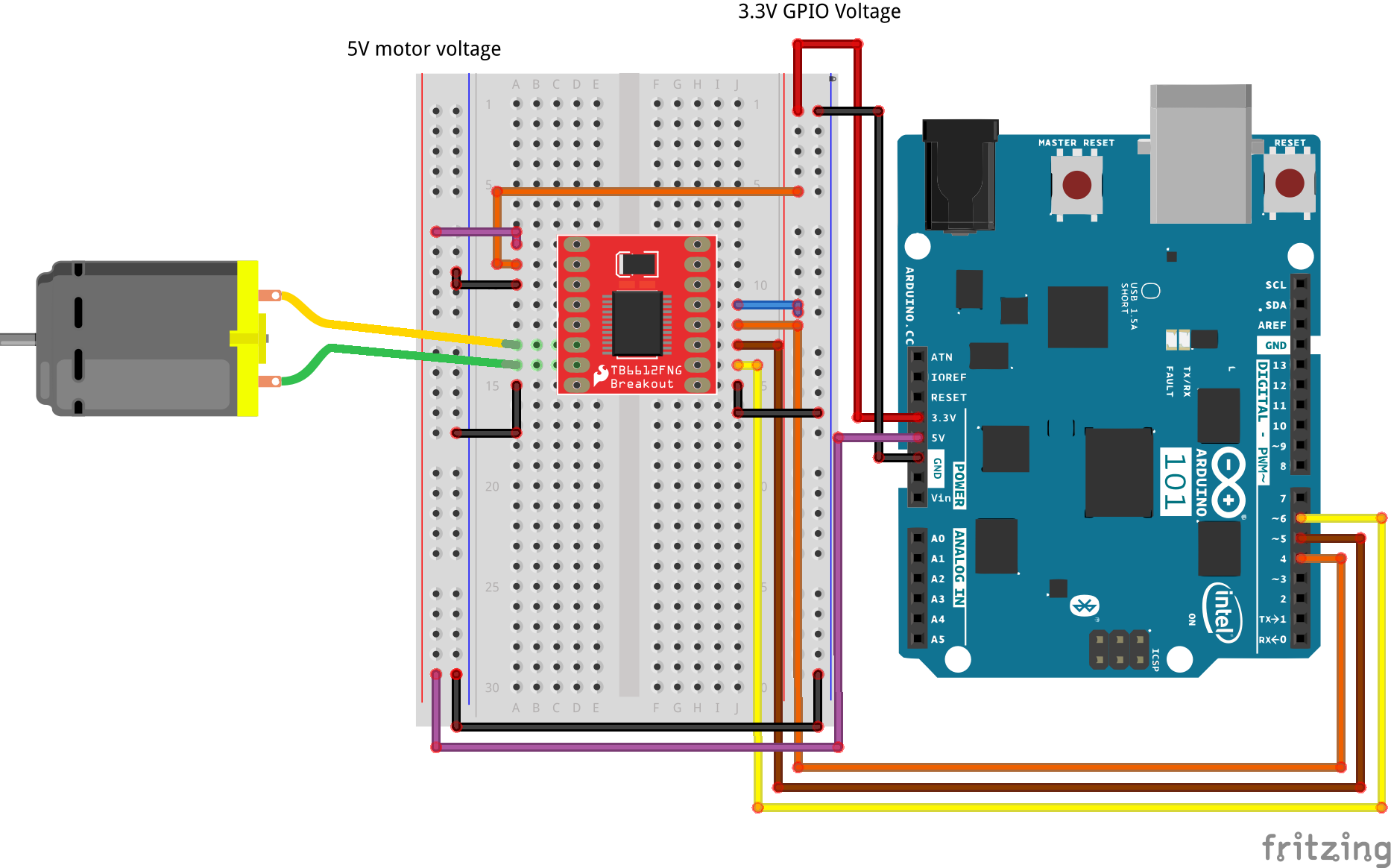
SIK Experiment Guide for the Arduino 101/Genuino 101 Board ...
Dedicated integrated circuits have dramatically simplified stepper motor driving. ... tween the phase current diagram and the control si-.17 pages

Schematic diagram of the stepper motor driver. | Download ...
The wiring diagram below shows you which connections you need to make. TB6600 stepper motor driver with Arduino UNO and stepper motor wiring diagram In this tutorial, we will be connecting the driver in a common cathode conguration.
Redrex Stepper Wiring Diagram
Stepper Motor Driver (74194). Probably the simplest, reversible drive circuit is the H-Bridge. Some BEAMbots use H-bridge motor drivers; many more use an H- ...
How to drive a stepper motor- simplified beginner's guide ...
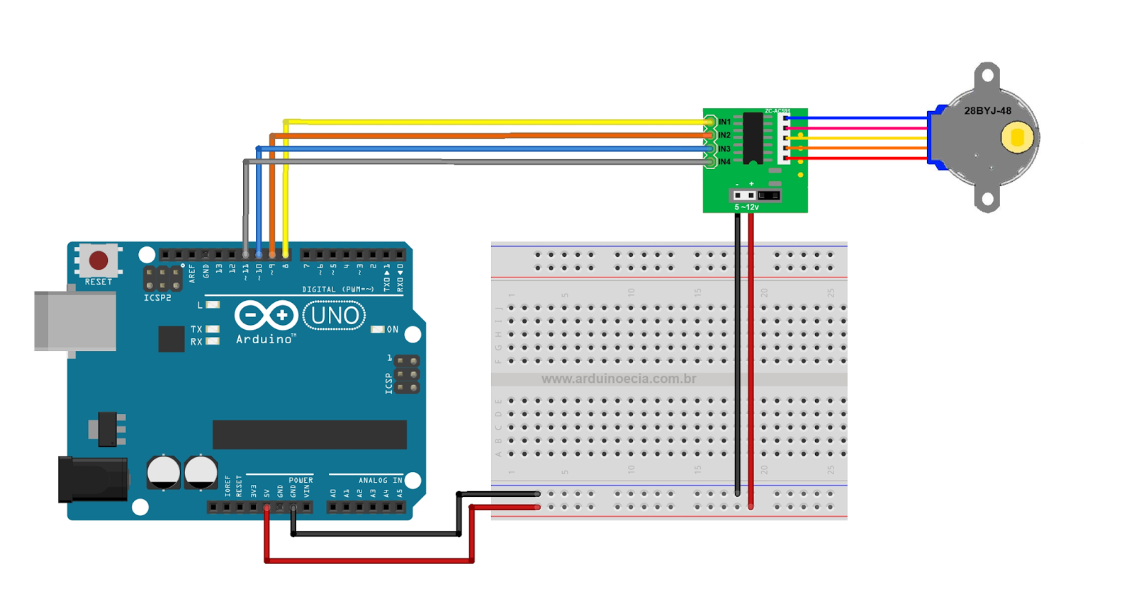
The circuit Diagram for the arduino stepper motor control project is shown above. We have used the 28BYJ-48 Stepper motor and the ULN2003 Driver module. To energise the four coils of the stepper motor we are using the digital pins 8,9,10 and 11. The driver module is powered by the 5V pin of the Arduino Board.

the one and only Saigon
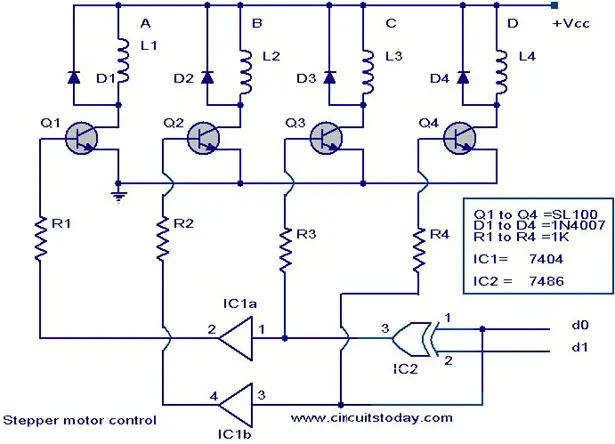
Description. Here is the circuit diagram of a simple stepper motor controller using only elementary parts. The driver circuit uses, four transistor (SL100) to drive the motor windings, two NOT gates and one XOR gate to decode the two bit control logic to drive the four windings of the motor.

Love the Bug
Bipolar Motor Driver Circuit Interfacing Diagram. A bipolar motor circuit diagram is shown below: There are three different ways in which we can drive the bipolar stepper motor: Only one of the phase winding is energized at a time. That is, either AB or CD is energized. Of course, the coils will be energized in such a way that we get correct ...
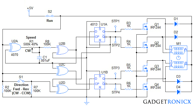
Stepper Motor Controller Circuit - Gadgetronicx
The UC3717A’s drive circuit shown in the block diagram includes the following components. (1) H-bridge output stage (2) Phase polarity logic (3) Voltage divider coupled with current sensing compa-rators (4) Two-bit D/A current level select (5) Monostable generating fixed off-time (6) Thermal protection OUTPUT STAGE
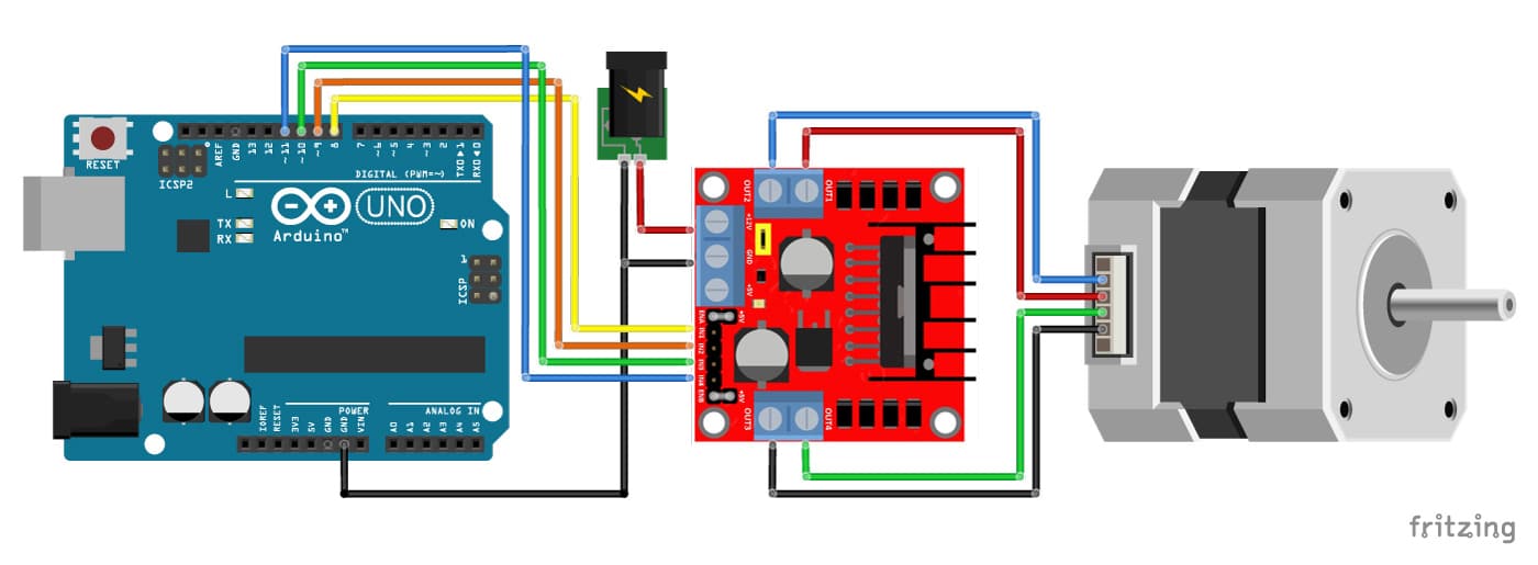
Stepper Motor with L298N and Arduino Tutorial (4 Examples)
1 component drives stepper Motor - The extremely simple circuit in Fig 1 drives a stepper motor directly from 12V ac , 60 Hz power supply. Usually you need switched-dc voltages to drive a stepper motor. But a stepper motor will run off ac lines if you introduce a 90° phase shift between the voltages applied to the motor's two windings.
18 Awesome Stepper Motor Wiring Diagram
Feb 24, 2012 · A stepper motor driver (or stepper motor drive) is a circuit used to drive or run a stepper motor. A stepper motor driver usually consists of a controller, a driver, and the stepper motor’s connections. A lot of driver circuits are available on the market today. Over time, these have been made to be easier and easier to interface to a stepper ...

Stepper Motor Driver (74194) | Stepper motor, Electronic ...
Stepper Motor Wiring Diagram – arduino stepper motor wiring diagram, cnc stepper motor wiring diagram, leadshine stepper motor wiring diagram, Every electrical structure is composed of various distinct pieces. Each component should be set and connected with different parts in particular manner. If not, the structure won’t function as it should be.

Patrouille de France Gp France
A Stepper Motor rotates precisely by synchronising the pulse signals from a controller, which are given through a Driver. A Stepper Motor Driver ...Jul 4, 2017 · Uploaded by Electronics HubIntroduction · Components Required · Component Description · Circuit Design

KoraÄni Motori & Drajveri: TB67S Stepper Driver
Circuit diagram: Stepper Motor Controller Circuit Diagram. IC3, IC4 and IC5 are all of this type (which is economically priced). Here IC3 and IC4 are wired as comparators. Their non-inverting inputs are driven by the previously mentioned I and Q signals, with the inverting inputs set to a potential equal to half the supply voltage.

Yellow Porsche 911

Stepper Motor Generator | Xtreme Circuits
Arduino lesson - Stepper Motor « osoyoo.com

Audi WEC No.7

C3D External Stepper Driver Wiring Diagrams - LaserGods.com

Drive Stepper Motor with IC UCN5804 | IC schematics
L298N Motor Driver Board - BC Robotics

Image from page 78 of "Cyclopedia of applied electricity : a general reference work on direct-current generators and motors, storage batteries, electrochemistry, welding, electric wiring, meters, electric lighting, electric railways, power stations, switc
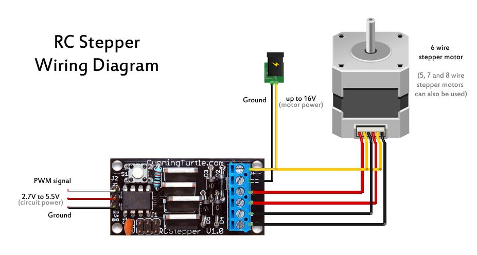
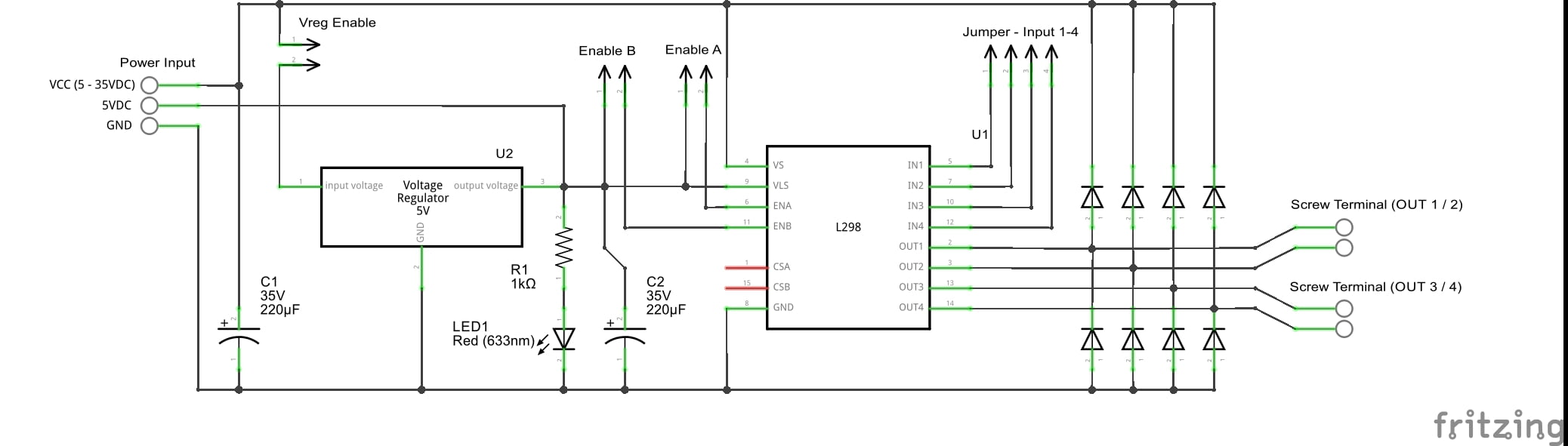
Radio Controlled Stepper - CunningWiki

Arduino Uno Stepper Motor Wiring Diagram

Stepper Motor Wiring Diagram - Wiring Diagram Schemas
Stepper Motor Driving Modes
Arduino Unipolar Stepper Motor Control - Simple Projects
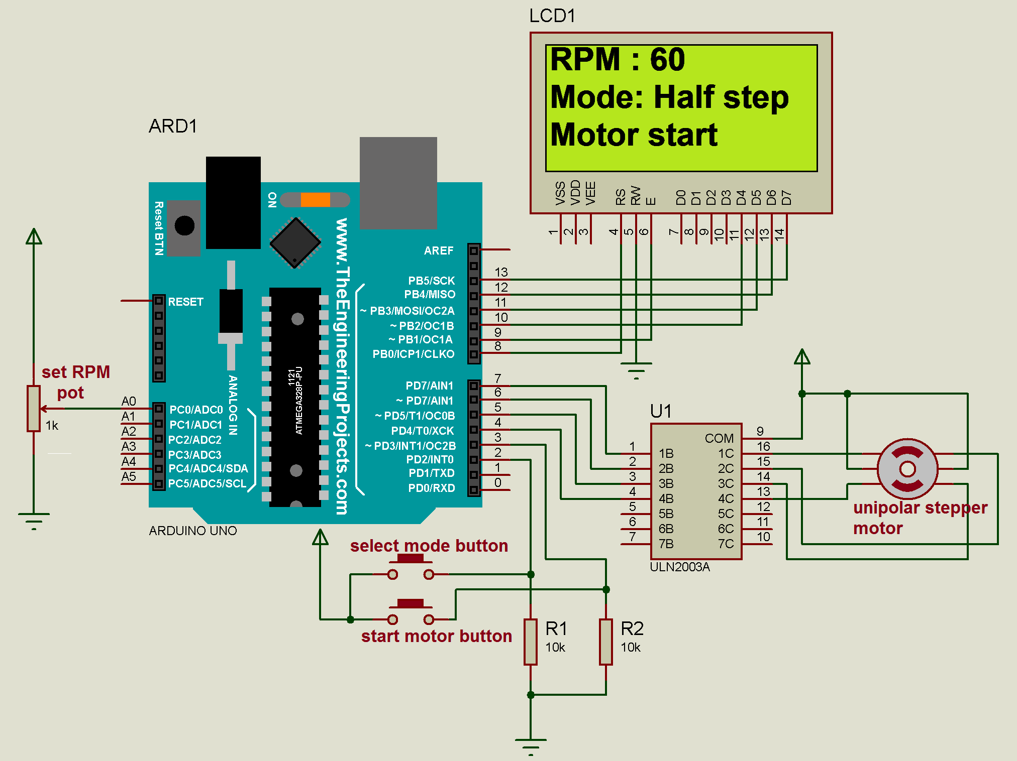
Diploma: Stepper Motor Control using 8051 Microcontroller

Juan Pablo Montoya in the #42 Chip Ganassi Racing Chevy sponsored by Target in the Brickyard 400 practice session in the 2009 NASCAR season.
0 Response to "38 stepper motor circuit diagram"
Post a Comment