39 dei 451m wiring diagram
Directed 451M (dei-451m) Door Lock Relay Module with Resistors Page 1/2. Read Book Directed 451m Installation Guide ... 29.09.2018 29.09.2018 1 Comments on 451m Relay Wiring Diagram. Also included in this guide are wiring diagrams for incorporating priority door locking cles, or if an actuator is to be installed, either Primary Harness Diagram 8 Wire Connection Guide 9 Plug in LED and Valet®/Program Switch 11 Four-pin Shock Sensor Harness 11 Bypassing Sensor Inputs 12 Door Lock Wiring Diagrams 12-15 Transmitter/Receiver Learn Routine™ 16 Two-vehicle Operation with Single Transmitter 17 Operating-Settings Learn Routine™ 18 New Double Pulse Unlock Feature
451m Relay Wiring Diagram - schematron.org Directed 451M. 4.8; 5 reviews. Door Lock Relay Module with Resistors DEI 451M ... • Includes module, wiring harness and installation guide. $9.03 Add to Cart. IN STOCK. Gallery. Directed 504KP. LED and Valet Pod for the 504K. $14.99 Add to Cart. AVAILABLE. Ships at Later Date. Gallery.

Dei 451m wiring diagram
A couple of threads discuss converting the VTS relay circuit over to a DEI 451M solid state relay module. I have the relay but no schematic for the internals. Has anyone done this mod for the rear mounted, encapsulated VTS module ('95, '96, '97...)? If so, which wire colors go together? Wire it like this: Actuators/Reverse Polarity Diagram The blue wire is your (-) unlock output and the green wire is your (-) lock output. Also, if you use a 451M, it should plug into the alarm brain in place of the 3-pin plug with the lock and unlock wires; in that case just ignore the 85s and 86s in the above diagram. Oct 6, 2016. #1. I am having trouble with the correct wiring to do a VTS module bypass on a 1995 SeaDoo 717 XP. Can anyone profide a diagram or link I could go to so I can do the right wire color connections between the harness and the 5 wire 451M bypass relay ? There are two black wires in the SeaDoo harness.
Dei 451m wiring diagram. Dei 451m installation manual Installation Points to Remember Page 2 Deciding on Component Location 3 Finding the Wires you Need 5 Step-by-step meter instructions! Making your Wire Connections 7 Primary Harness Diagram 8 Wire Connection Guide 9 Plug in LED and Valet®/Program Switch 11 Four-pin Shock Sensor Harness 11 Bypassing Sensor Inputs 12 ... Title: Print 2451111.DCX (6 pages) Author: Eugene@TECH3 Created Date: 10/30/2002 4:11:56 PM Directed 451M (dei-451m) Door Lock Relay Module with Resistors Page 1/2. Download Free Directed 451m Installation Guide ... 29.09.2018 29.09.2018 1 Comments on 451m Relay Wiring Diagram. Also included in this guide are wiring diagrams for incorporating priority door locking cles, or if an actuator is to be installed, either immobilizer harness wiring diagram ___ ___ ___ immobilizer harness wiring guide h2/1, h2/2, and h2/3 black immobilizer pigtail harness The starter immobilizer harness can be installed as a normally open or normally closed circuit by connecting the desired side of the three-wire immobilizer. Locate the
Aug 10, 2018 · 451m Relay Wiring Diagram. 29.09.2018. 29.09.2018. 1 Comments. on 451m Relay Wiring Diagram. Also included in this guide are wiring diagrams for incorporating priority door locking cles, or if an actuator is to be installed, either a M Door Lock Relay . View and Download Directed 451m manual online. Door Lock Interface. 451m locks pdf manual download. Dei 451M Wiring Diagram - New Viper Dei 451m Door ... Hayward Aqua Pod Manual - Large Pool Leaf Canister... Manual De Bienvenida - Manual De Bienvenida Calame... Yaesu Ft 736R Manual : Yaesu Ft 736r Ft 747gx Ft 8... Reliamed Blood Pressure Monitor Manual / Reliamed ... Summer Worksheets For 5Th Graders : Free 5th Grade... Dei 451m manual. Без рубрики ... The (+) terminal of the battery, or the constant supply to the ignition switch. · m Relay Wiring Diagram. 1 Comments. on m Relay Wiring Diagram. Also included in this guide are wiring diagrams for incorporating priority door locking cles, or if an actuator is to be installed, either a M Door Lock ...
Install Essentials 451M Dooor Lock Relay Module. 4.6 out of 5 stars. 293. 6 offers from $16.56. Universal Door Lock Relay Kit Module Triggered by Negative Pulse. 4.4 out of 5 stars. 22. 2 offers from $14.95. Directed Install Essentials 451M Door-Lock Relay Assembly. Refer to the vehicle-specific wiring instructions on the web and the chart below to help determine which door lock system your vehicle uses. Note: The more common type of door lock systems are Type A or Type B. Any other, Types C thru H, will require external relays or a Directed Electronics 451M. Jersey. Mar 14, 2006. #7. you need to cut your factory door lock wires and use relays to make the locks work. This is a 5 wire setup, it can be accomplished with part number dei 451m, or you can use two relays and make your own. Do a search on 5 wire door locks and you should be able to find a diagram fairly easy. C. Dec 10, 2020 · Dei 451M Wiring Diagram. To properly read a electrical wiring diagram, one provides to learn how the components in the method operate. For example , in case a module is powered up and it sends out a signal of half the voltage plus the technician does not know this, he would think he provides an issue, as he or she would expect a new 12V signal ...
DLRM DLS car door lock relay module features two on-board ...
29.09.2018 29.09.2018 1 Comments on 451m Relay Wiring Diagram. Also included in this guide are wiring diagrams for incorporating priority door locking cles, or if an actuator is to be installed, either a M Door Lock Relay . ...

Amazon.com: Install Essentials 451M Dooor Lock Relay Module ...
Feb 23, 2005 · Joined: January 25, 2005. Posted: February 23, 2005 at 10:25 PM / IP Logged. How do I wire the DEI 451M up with two 5-wire actuators? They came with their own relay also. I want them to work with the alarm remote as well as work together. So if I manually unlock one it unlocks the other. I appreciate any help.

DIY Aurduino LED Game : 8 Steps - Instructables
My next project is installing the CompuStar Remote Start (model #1W900FMS). I thought I would post the wiring installation diagram and get comments before cutting any wires. One of the 12 volt constant inputs (red wire) I still have questions about. It is the second +12 volt constant input to the remote start module as shown in the diagram below:
anyone here install a viper 791xv on their S2000? - Honda ...
Re: VTS Bypass Fix. I think he is talking about the DEI 451M. Intended to control auto door locks on alarms but apparently works well for failed VTS boxes. I will be buying one soon but was hoping to find an owners manual/direction for the unit first. These are all over ebay, I plan to buy a few of them. 05-28-2009, 12:24 AM #4.

2000 Durango SLT Alarm/Keyless/Remote Start HELP!!! | Dakota ...
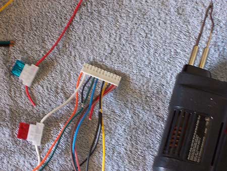
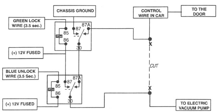
1 Lock - trigger w/ 1.4K Ω resistor, unlock - trigger w/ 426 Ω resistor. Use DEI 451M relay. 2 In the top left corner in a black plug. 3 Park light - trigger w/ 910 Ω resistor. Headlight - trigger w/ 349 Ω resistor. Use relays. 4 Drvr door trigger tan, pass'er door trigger tan/white, use both wires, diode isolate each.

DIY: FC RX7 Window Switch Relay Mod PnP T-Harness - RX7Club ...
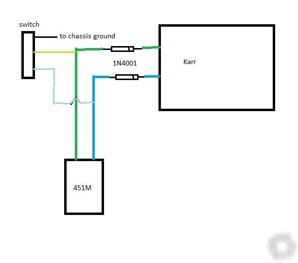
No, if you read the post we are trying to use the DEI 451M relay, which is two relays built into one module. That is why we are having issues. Using one SPDT relay would work with the above diagram, however the DEI is different - or at least we cant figure out how to wire it like the diagram I posted.

451m Setup and Explanation - YouTube
Download Free Directed 451m Installation Guide vehicle due to improper installation. Please call tech support at 1-877-289-7664 if you require additional assistance. Directed 451M (dei-451m) Door Lock Relay Module with Resistors Features. Overview: The door lock relay module (451M) will interface with most Page 12/24

Amazon.com: Install Essentials 451M Dooor Lock Relay Module ...
H13 Bulb Wiring Diagram : How To Install And H13 H... Escort Mk1 Wiring Diagram / De Luxe Post 1969 Wiri... Raupe Bilder Zum Ausmalen / Die Kleine Raupe Nimme... Car Alarm Relay Diagram Domelight / Pf K Documentp... Dei 451M Wiring Diagram : Dei 451m Door Lock Modul... Connect Electrical Wiring / Awesome Idea How To Co...

Directed 451M | Door Lock Relay Module - Sonic Electronix
This 451M makes it easy to wire because is is basically two relays in one simple package. It comes with easy to follow instructions and when used with remote key entry systems and/or spring loaded switches works like a charm.
Stealth car alarm install - 2nd Generation Acura Integra DA
Size: 198.56 KB. Dimension: 1211 x 891. DOWNLOAD. Wiring Diagram Images Detail: Name: avital 4×03 remote start wiring diagram - switch wiring on directed electronics remote start wiring diagram rh kbvdesign co Dei 451M Wiring Diagram Viper Remote Start Wiring Diagram. File Type: JPG.

Viper Directed Install Essentials Micro Pre-Wired Door Lock ...
Download. DEI VIPER 560XV MANUAL PDF. Dei viper 5000 car alarms, owners guide 61 pages Summary of Contents for Viper 5901. Featuring, Viper, Hornet, Avital, Clifford Parts, Xpresskit, Autostart, Orion Cobalt, Your Valet, Python. Viper SmartStart with GPS and Viper 2-way security overview. DEI HP104 Single Channel IR Headphones HP060.
Variation of installation of a power tailgate lock on 2019 ...
The relays i like to use are DEI 451M, you need just one because they actually a relay pack, I have a few here because ive been installing alarms and starters. if you need just one let me know. i'll let it go cheap I have 3 relays that were part of the power windows/locks (I think). I'm not that great with wiring at all.

Buy DEI 451M DOOR LOCK RELAY in Clinton, New Jersey, United ...
These Directed Electronics internal door lock relays can get confusing, This wiring how to explains how these work on all Viper, Clifford, Automate and Pytho...

Viper Directed Install Essentials Micro Pre-Wired Door Lock ...
Oct 6, 2016. #1. I am having trouble with the correct wiring to do a VTS module bypass on a 1995 SeaDoo 717 XP. Can anyone profide a diagram or link I could go to so I can do the right wire color connections between the harness and the 5 wire 451M bypass relay ? There are two black wires in the SeaDoo harness.
VIPER 300+ INSTALLATION MANUAL Pdf Download | ManualsLib
Wire it like this: Actuators/Reverse Polarity Diagram The blue wire is your (-) unlock output and the green wire is your (-) lock output. Also, if you use a 451M, it should plug into the alarm brain in place of the 3-pin plug with the lock and unlock wires; in that case just ignore the 85s and 86s in the above diagram.
DEI546 554 IVU User Manual N554V 11-02.qxd DEI Headquarters, .
A couple of threads discuss converting the VTS relay circuit over to a DEI 451M solid state relay module. I have the relay but no schematic for the internals. Has anyone done this mod for the rear mounted, encapsulated VTS module ('95, '96, '97...)? If so, which wire colors go together?

DEI 451m wiring?
Variation of installation of a power tailgate lock on 2019 ...

Wiring How To on DEI Viper 451m Type Internal Door Lock Relay ...
DEI546 554 IVU User Manual N554V 11-02.qxd DEI Headquarters, .
Alarm install question | StangNet
Installing Actuators

help with door lock wires for viper 5002 alarm - S2KI Honda ...

VIPER DIRECTED INSTALL Essentials Micro Pre-Wired Door Lock ...
PYTHON 1000HF - инÑÑ‚Ñ€ÑƒÐºÑ†Ð¸Ñ Ð¿Ð¾ уÑтановке

NEW VIPER DEI 451M Door Lock Relay Assembly Module Remote ...
DEI 451m relay question

DEI 451m wiring?

Dei 451M Door Lock Module Relay Pack Car Remote Start Alarm ...
Stealth car alarm install - 6th Gen Honda Civic EK
Central Door Lock Switch to 451M Relay

XpressKit DLPK

Dodge ram keyless entry lock unlock wiring
5 wire relay/door lock + alarm | TCCoA Forums
Car☆Com Model 400

I have a 2001 Chevy silverado pickup 1/2 4x4. Viper system ...
Installed Power Door Locks to my JL Sport | Jeep Wrangler ...
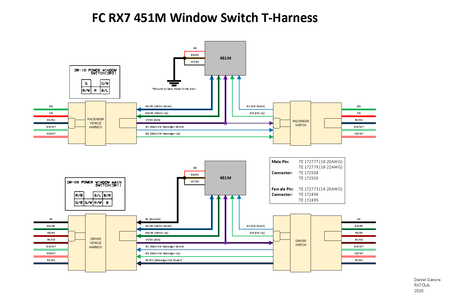
DIY: FC RX7 Window Switch Relay Mod PnP T-Harness - RX7Club ...
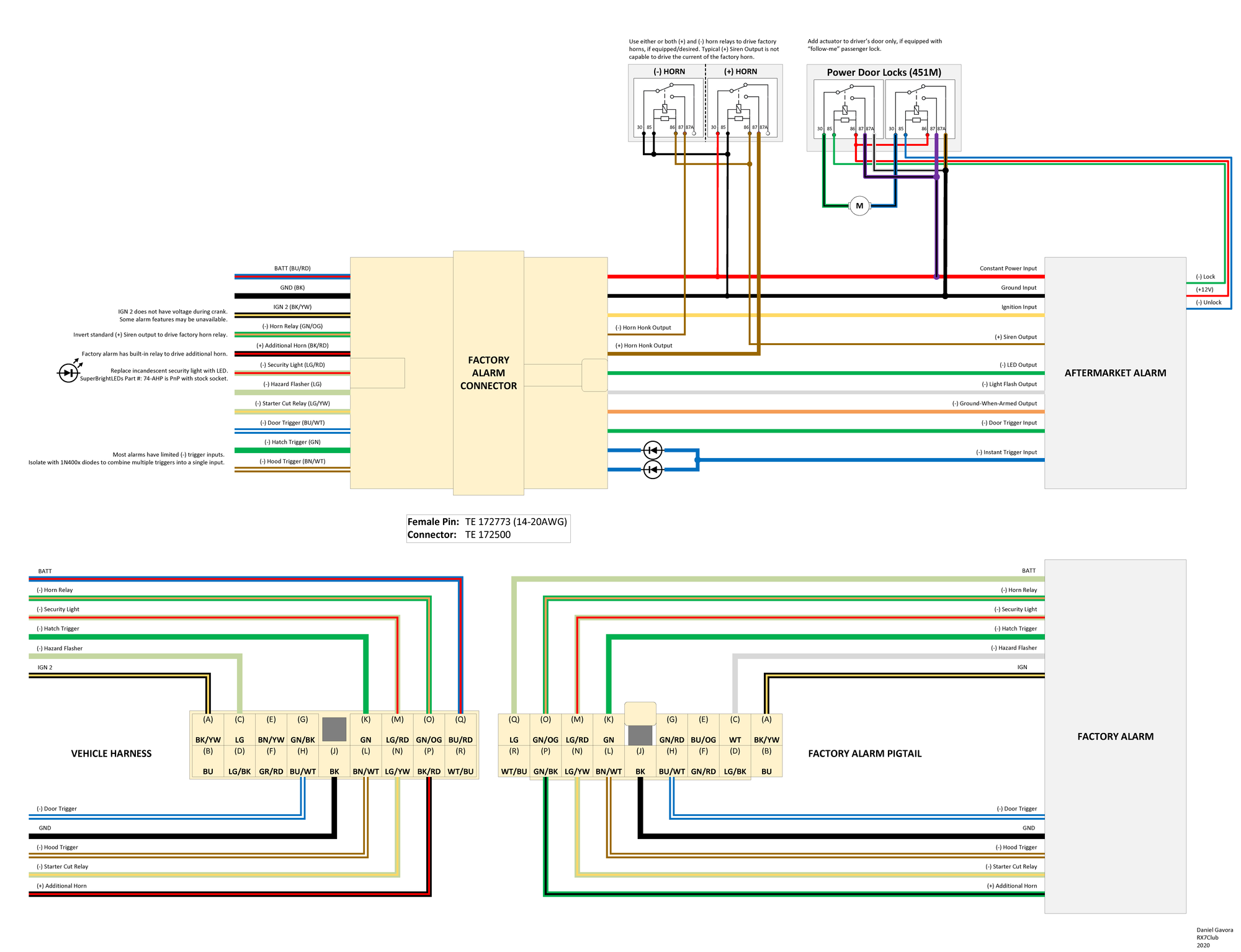
DIY: FC S4 RX7 aftermarket alarm PnP harness - RX7Club.com ...
0 Response to "39 dei 451m wiring diagram"
Post a Comment