36 5 wire regulator rectifier wiring diagram
› wiki › indexWilliams WPC - PinWiki Feb 25, 2022 · Note that the LM317 is an adjustable voltage regulator where the LM323K is a 5V specific regulator. The LM317 is "programmed" to 5.108V using precision resistors R1 (750 ohms) and R2 (243 ohms), located just to the right of the LM317 heat sink. 6 Wire Rectifier Wiring Diagram - U Wiring Auto parts accessories 4 wire full motorcycle regulator rectifier tester voltage wiring harley a for mosfet kawasaki 6 universal 12 volt units atv gy6 50 150cc scooter wires 5 2 phase pma install too high 3 and rectifiers wave black motored pins flwd suzuki 32800 30b01 12v lucas regulators diagram pin with. 6 volt solid state regulator rectifier.
6 Wire Regulator Rectifier Wiring Diagram - Wiring Sample Fd8d7c1 6 wire voltage regulator wiring diagram. 2 phase 5 wire motorcycle regulator rectifier wiring diagram pdf. A few notes I pulled this schematic out of an older scooter repair manual. A wiring diagram is a schematic type that uses abstract illustrated symbols to show all of the components of a system.
5 wire regulator rectifier wiring diagram
how to wire rectifier - shapovmusic.com 5 wire regulator rectifier wiring diagram 3 pin regulator rectifier wiring diagram 3 wire rectifier diagram kbpc5010 bridge rectifier wiring diagram how to wire stator and rectifier 12v rectifier regulator diagram motorcycle. See more articles in category: FAQs. About shapovmusic_admin. 5 Pin Regulator Rectifier Wiring Diagram - Wiring Tech 5 Pin Regulator Rectifier Wiring Diagram August 15, 2021. Puch Wiring Mopedwiki Motorcycle Wiring Puch Electrical Diagram . 110 Cc Atv Five Wire Cdi Diagram 110cc Chinese Quad Wiring Diagram Wiring Diagram Roy Evans 301 Moved Perm Motorcycle Wiring 150cc Scooter 150cc Go Kart . Atomic Dirt Bike 250 Wiring Diagram Wiring Diagram Amp Cable ... SUZUKI - Motorcycles Manual PDF, Wiring Diagram & Fault … 02.03.2022 · I need a wire diagram for a 2005 tank vision 250R3 can't figure out to connect control switch to the wires they have different colors from the control switch to the wire harness #715. Kef (Saturday, 26 February 2022 15:56) Can u give me sym 185 vf3i wiring diagram #714. Falak (Saturday, 26 February 2022 11:13) Suzuki 150 SE Right indicator doesn't work. Wiring …
5 wire regulator rectifier wiring diagram. Electronic Components Distributor | Pinout, Circuit ... Apogeeweb Electronic components online offers a huge selection of high-quality products. Learn about various electronic components with their pinout details, uses, applications and … 5 Wire Rectifiers.... Your regulator has to match the stator you have. You either have the wrong regulator or a bad one. If you don't have a 5 wire hook-up, try going with a 4 pin reg. Put the Yellow and white diagonal from each other and the green and red diagonal from each other on the other 2 pins. Dave @ Absolutely Scooters. 5 Pin Rectifier Wiring Diagram - easywiring Regulator rectifier 7003 rr150 tech support. 5 pin rectifier wiring diagram wiring diagram is a simplified agreeable pictorial representation of an electrical circuit it shows the components of the circuit as simplified shapes and the faculty and signal contacts amongst the devices. › harley-davidsonHARLEY DAVIDSON - Motorcycles Manual Pdf, Wiring Diagram ... Hi, does anyone have a wiring diagram for lexmoto assault efi 2019, the ignition switch they sell on cmpo doesn't fit to wiring loom on bike:))). They is a 6 pin plug with red, black and brown on bike and an 6 pin plug with red, black, green, black/white on ignition switch all of them in completely different positions.
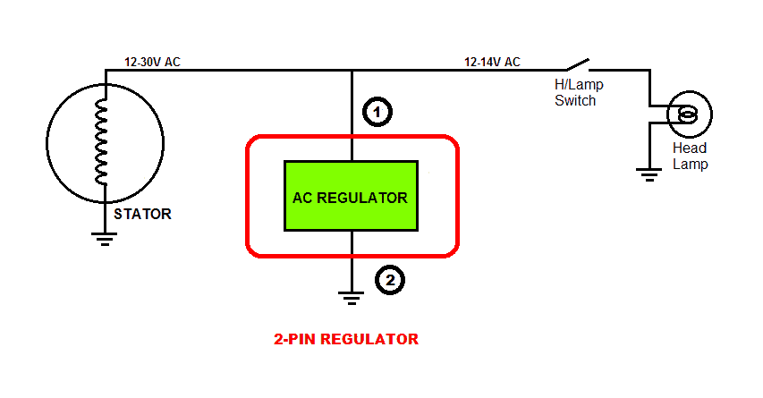
Wiring Diagram: 5 Pin Rectifier Wiring Diagram. Jeff ... May 11, 2018 - Wiring Diagram: 5 Pin Rectifier Wiring Diagram. Jeff Sessions 2nd ... Lambretta 5 Pin Regulator Wiring Diagram - schematron.org rectifier/regulator go along with the other items running on the electrical system; Here is a wiring diagram of the typical 5-wire CDI system on a lot of scooters comprising pick-up input, battery +12 volts in, Gnd, and Ignition coil out pins.some common electrical setups and included the wiring diagrams. PDF 150cc Regulator Wiring Diagram charging system battery firenzee com, pitbike rectifier regulator wiring diagram, gy6 rectifier diagram wordpress com, 5 wire rectifiers, ruckus gy6 swap wiring diagram, 1977 ford f 150 wiring diagram voltage regulator wiring, rectifier for gy6 150cc wiring diagram roshdmag org, below is a schematic of a typical scooter electrical set, gy6 › cgi-bin › viewit301 A John Deere Industrial diesel - Yesterday's Tractors If all still original the regulator connection is a plug in to the matching connector in the harness located withing the length of the wires on the regulator. If the plug-in connector has been cut off the regulator or from the harness, I will ask if it still has the original Motorola alternator or if someone has installed a Delco.
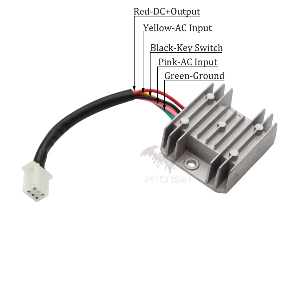
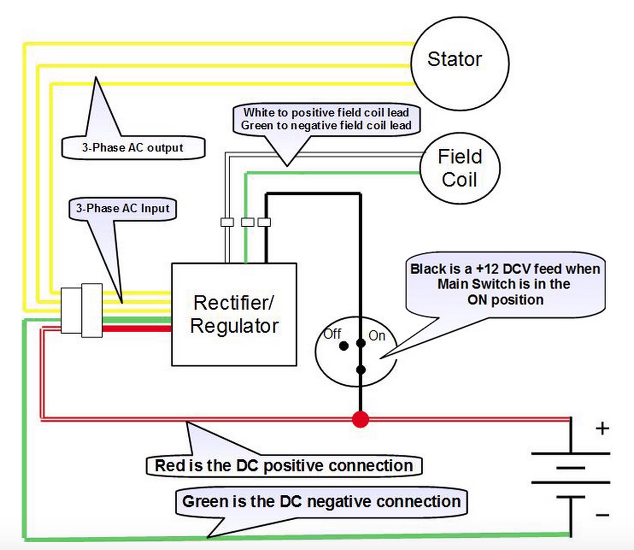
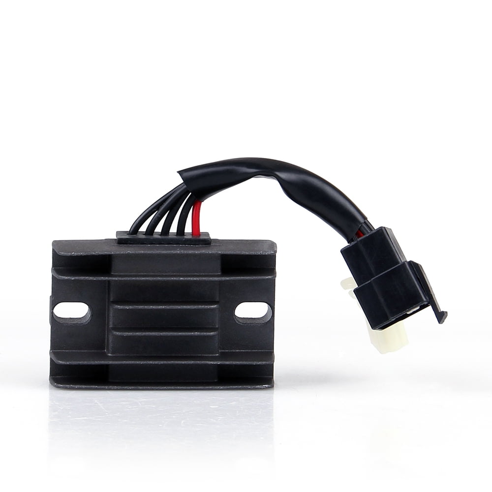
PDF Regulator/Rectifier Wiring Guide Wiring for Small ... REGULATOR/RECTIFIER 7003-RR150 Tech Support: 360-687-4530 REGULATOR/RECTIFIER tech_support@trailtech.net WIRING GUIDE WIRING FOR SMALL BATTERIES UNDER 4 Ah: Trail Tech Regulator/Rectifier 7003-RR150 2 Yellow Wires: Red Wire: Blue Wire: Black Wire: Lighting leads. Connect to lighting leads from stator. Trail Tech stators have yellow lighting leads. Recitifer Regulator Signal Wires - Rick's Motorsport ... Recitifer Regulator Signal Wires. Many Rick's Motorsport Electrics Rectifier/Regulators eliminate what is commonly referred to as a "signal wire" on OE pieces. For example, on a 1981 Kawasaki KZ440, there are 5 wires going to the OE part: 2 yellow wires (AC inputs), white/red (DC "+" output), black/yellow (DC "-" output), and a ... Regulator-rectifier only has 5 wires??? - KZRider Forum ... Any 3-wire aftermarket reg/rec with a total of 5 wires will be the hot wire as described (prolly the red wire), the black/white is prolly the ground and the yellows are stator connection wires. The reg/rec is a more modern type that senses voltage via the red wire. Rectifier Regulator Wiring Diagram For 150cc Chinese - Wire Regulator Rectifier Combo With Points Wiring Diagram Motorcycle . How to wire a gy6 scooter regulator rectifier and how it all works part 3 the regulator. Rectifier regulator wiring diagram for 150cc chinese. If you find that your electrical system overloads when you rev up the machine then you most likely need to replace the voltage regulator.
5 wires Voltage Regulator Rectifier for GY6 125cc 150cc 200cc ...
Rectifier Regulator Wiring Diagram - Wirings Diagram Rectifier Regulator Wiring Diagram - 12v rectifier regulator wiring diagram, atv regulator rectifier wiring diagram, honda regulator rectifier wiring diagram, Every electric structure consists of various distinct components. Each part should be placed and linked to different parts in particular way. Otherwise, the arrangement will not work as it ought to be.

Universal regulator rectifier
› d1 › garage1957 Passenger Assembly Manual - Chevy Tri Five Forum Wiring Diagram (Right Drive) Sheet 28.00 Wiring Diagram FOA (Left Drive) Sheet 28.01
Amazon.com: XLJOY 5 Wire Voltage Regulator Rectifier For Baja ...
How to identify Honda wire colors - 4-stroke.net 05.08.1991 · It breaks down the color-codes used with most of our bikes (the one exception is described in a footnote) and even tells you where each wire begins and ends. The August Full Cycle release, "How to Read Honda Wiring Diagrams", will refer you to this chart so please keep it around as d reference. Copies won't be included with the program, but you ...

Voltage Regulator - 5 Wire / 1 Plug for 250cc ATV - Version 45
5pin Regulator rectifier wiring diagram(paano malalaman ... 5 pin regulator rectifiier wiring diagramSana makatulong po ito sainyo mga bro.Para sa iba pang vidio wag nyo pong kalimutan magSUBSCRIBELIKE AND SHARETO GOD...

half wave 12v rectifier regulator solution for puch and ...
How to Make a Bench Power Supply : 20 ... - Instructables How to Make a Bench Power Supply: A bench power supply is an extremely handy bit of kit to have around for electronics hobbyists, but they can be expensive when purchased from the market. In this Instructable, I will show you, how to make a …
Motorcycle Regulator Rectifiers 5 Wires Plug for Yamaha ...
› 2021 › 02Simple Cell Phone Charger Circuit Diagram - 5V from 230V AC Then heat generated is (12V – 5V) x 0.5mA = 3.5 Watts. So a heat sink can be attached which can absorb heat of 3.5 watts of power to avoid the IC getting damage. 7805 voltage regulator IC signifies two meanings: “78” means positive and “05” means 5 volts, hence this IC is used to supply positive 5 volts DC supply.

Voltage Regulator Rectifier 5 Wires 5 pin 12V GY6 scooter ATV ...
5 Wire Regulator Rectifier Wiring Diagram - Studying Diagrams 5 wire regulator rectifier wiring diagram. -new green replace old green. Rectifierregulator go along with the other items running on the electrical system. It shows the components of the circuit as simplified shapes and the faculty and signal contacts amongst the devices.
LYUMO Voltage Regulator Rectifier, Voltage Rectifier ...
4 wire / 5 wire regulator rectifier wiring diagram and ... All about motorcycleJHAY'D MECHANIC
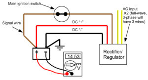
Recitifer Regulator Signal Wires – Rick's Motorsport ...
5 Pin Rectifier Wiring Diagram - U Wiring Vacuum Diagram As Well 2001 Ford F 150 5 4 Vacuum Line Diagrams On size. 5 pin rectifier wiring diagram. On the solder side of. Reddit gives you the best of the internet in one place. Design a regulated DC power supply of 5V which can be used to run a LED using AC voltage as the input.

Buy ATV GY6 50 150cc Scooter 4 Wires Voltage Regulator ...
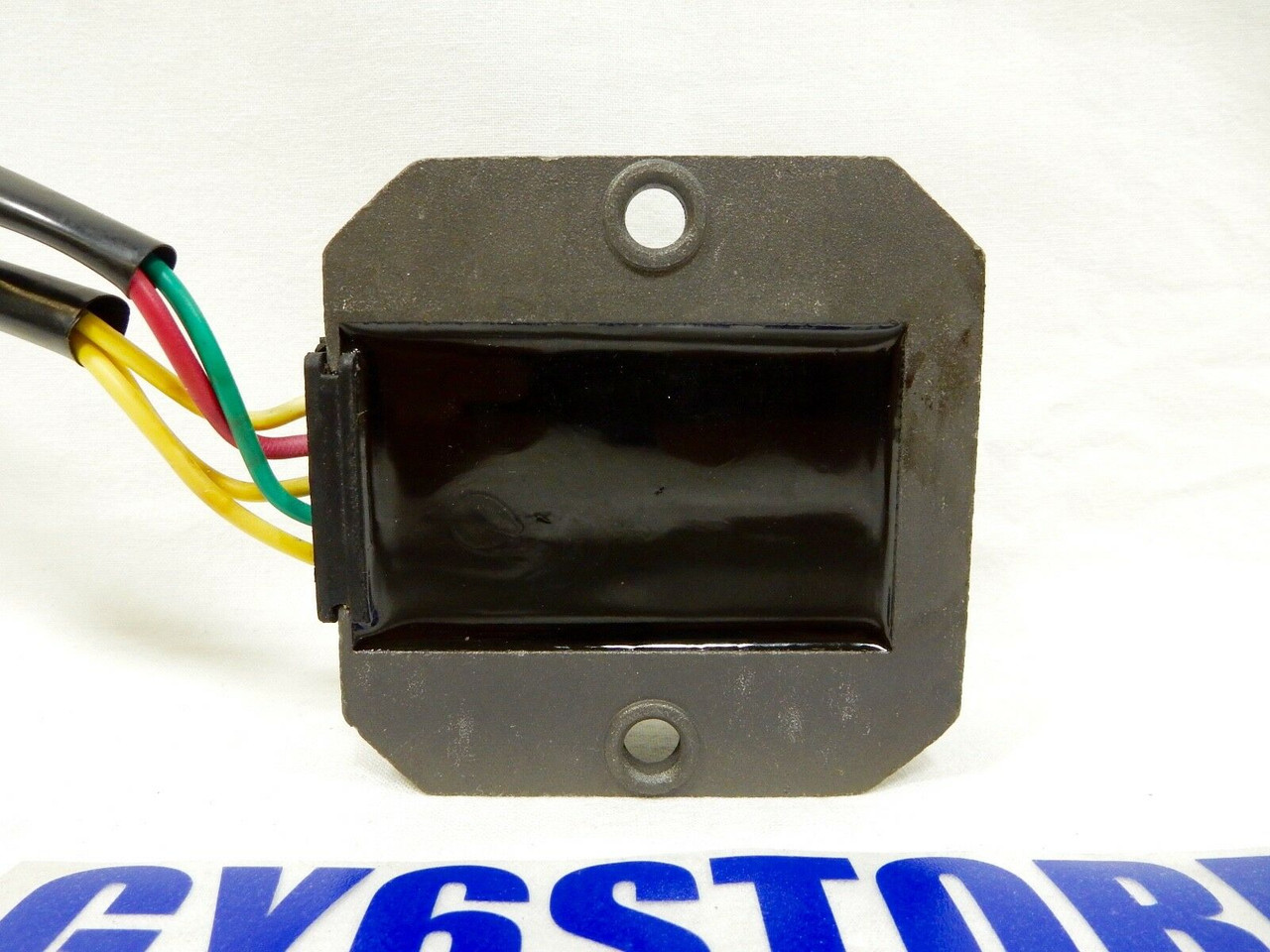
5 wire rectifiers - Oregon motorcycle Parts Home Page A combination regulator / rectifier for. the 1979~1983 DOHC Honda 750~1100 can be found on my regulator / rectifier units page. All the rectifiers on this page are rated at is rated at 55 amps constant use. Most OEM 5. wire rectifiers are only rated at 18 to 22 amps. All the rectifiers on this page have 5 wires except where noted.
Price history & Review on GY6 50 150cc Scooter Voltage ...
› ac-dc-powersingle-phase-full-wave-controlled-rectifier | AC-DC Power ... • The single phase fully controlled rectifier allows conversion of single phase AC into DC. Normally this is used in various applications such as battery charging, speed control of DC motors and front end of UPS (Uninterruptible Power Supply) and SMPS (Switched Mode Power Supply).

Universal MOSFET regulator rectifier
Regulator/Rectifier Replacement It's really not that hard to replace your regulator/rectifier. I will assume that you ... Some parts have 5 wires, some 6, some 7, and you have to know.7 pages

Buy Regulator Rectifier for Mercury Mariner Outboard 5 Wire ...
Motorcycle Regulator Rectifier Wiring Diagram How to wire a gy6 scooter regulator rectifier and how it all works part 3 the regulator duration. The article was submitted by mr. The color code remains the same. Regulator rectifier diagram here you are at our site this is images about regulator rectifier diagram posted by maria nieto in wiring category on may 08 2019.

18+ Motorcycle 4 Wire Ignition Switch Diagram - Motorcycle ...
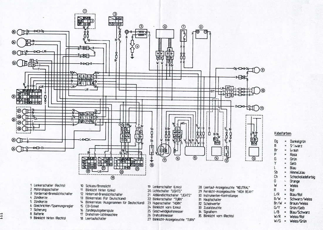
YAMAHA YZF-R15 SERVICE MANUAL Pdf Download | ManualsLib ECU wiring harness clamp 2. Wire harness 3. Starter motor lead 4. Rear brake light switch lead 5. Rear brake hose 2-38... Page 58 CABLE ROUTING 2-39... Page 59 CABLE ROUTING 1. Front brake hose 2. Throttle cable 3. Left handlebar switch lead 4. Clutch cable 5. Wire harness (to horn) 6. Ignition coil 7. Air filter case silencer hose 8. Sidestand switch lead 9. Coolant …
Wiring new rectifier to Indiana 650. 6 wires stock, can I use ...
Motorcycle Regulator Rectifier Wiring Diagram - Collection ... Following diagrams is fairly simple, but making use of it inside the scope of how the device operates is a new different matter. The best advice is not necessarily only look from the diagram, yet understand how the components operate when in use. Motorcycle Regulator Rectifier Wiring Diagram Source: .
Understanding Motorcycle Voltage Regulator Wiring - Homemade ...
150cc Gy6 Voltage Regulator Wiring Diagram Universal Parts 12 Volt 6 Amp YTX7A-BS Battery - Maintenance Free Dry AGM 12, , 5 pin Regulator for cc and cc GY6 engines commonly found Universal Parts Complete Wiring Harness for cc and cc 4-stroke GY6. rectifier/regulator go along with the other items running on the electrical system; stator common on most 50cc scooter but also can be found ...
Voltage Regulator 5 WIRE for GY6 125/150cc Engines: ModCycles
6 Wire Regulator Rectifier Wiring Diagram - Studying Diagrams Connecting the rectifier - Disconnect the 6-position 5 wire connector from the OE rectifier plug the. As stated earlier the lines at a Rectifier Regulator Wiring Diagram signifies wires. Simply plug the connector onto the 5 pins row and make sure that the pin assignments and wire assignments are matched correctly.
12V 5 WIRE VOLTAGE REGULATOR RECTIFIER FOR HONDA CN250/CF250 250cc 300cc SCOOTER
5 Wire Regulator Rectifier Wiring Diagram - easywiring 5 wire regulator rectifier wiring diagram. May 11 2018 wiring diagram. Wiring diagram for voltage regulator. 2 yellow wires ac inputs white red dc output black yellow dc output and a brown wire. How to wire the 5 cables not in a row. The yellows all come from the alternator you can connect these in any order to each other the red wire from the ...

Buy Voltage Regulator Rectifier Fits for Mercury Marine ...
5 Wire Regulator Rectifier Wiring Diagram 5 Wire Regulator Rectifier Wiring Diagram- One of the most difficult automotive fix tasks that a mechanic or repair shop can consent is the wiring, or rewiring of a car's electrical system.The pain really is that all car is different. in the manner of grating to remove, replace or repair the wiring in an automobile, having an accurate and detailed 5 wire regulator rectifier wiring diagram ...

5 wire rectifiers
Polaris Voltage Rectifier Regulator Wiring Diagram panel where the rectifier are open, causing high "ripple" or A/C voltage (while charging volts and amps are still. I replaced the voltage regulator (aftermarket, not Polaris), and I thou Polaris had a 3-wire regulator-rectifier that was used on sleds with electric start. Studying the wiring diagram a bit more, I can see that elec start sleds.
Magneto/Regulator Wiring for 2 to 4 stroke swap | Pocketbike ...
A Regulator To How Rectifier Wire [84BI26] Search: How To Wire A Regulator Rectifier. About A Wire How Regulator Rectifier To

5 wire voltage regulator? | Polaris ATV Forum
Rectifier Regulator Wiring Diagram - Wiring Sample Provided below is an online pdf document for lamberts bikes 3 phase 6 wire regulator rectifier wiring diagram. How to make a reliable motorcycle voltage regulator. Panel where the rectifier are open causing high ripple or a c voltage while charging volts and amps are still. Trail tech regulator rectifier 7003 rr150 2 yellow wires.
Aftermarket Honda Regulator Rectifier | OEM Style Honda ...
Putting a 6 wire rectifier on a 5 wire ... - Bike Chat Forums Can a 6 wire rectifier be put on a bike with a 5 wire rectifier. ... but looking closely at the circuit diagram the green and reds both merge into a single wire shortly after the connector. ... I have to say when I fitted a Honda regulator on my GS550 I had an extra wire that had to be connected to a switched live (I used the feed to the ...

Amazon.com: Voltage Regulator Rectifier for Mercury Mariner ...
SUZUKI - Motorcycles Manual PDF, Wiring Diagram & Fault … 02.03.2022 · I need a wire diagram for a 2005 tank vision 250R3 can't figure out to connect control switch to the wires they have different colors from the control switch to the wire harness #715. Kef (Saturday, 26 February 2022 15:56) Can u give me sym 185 vf3i wiring diagram #714. Falak (Saturday, 26 February 2022 11:13) Suzuki 150 SE Right indicator doesn't work. Wiring …

Mercury Mariner Outboard Force Voltage Regulator Rectifier 5 Wire 194-5279
5 Pin Regulator Rectifier Wiring Diagram - Wiring Tech 5 Pin Regulator Rectifier Wiring Diagram August 15, 2021. Puch Wiring Mopedwiki Motorcycle Wiring Puch Electrical Diagram . 110 Cc Atv Five Wire Cdi Diagram 110cc Chinese Quad Wiring Diagram Wiring Diagram Roy Evans 301 Moved Perm Motorcycle Wiring 150cc Scooter 150cc Go Kart . Atomic Dirt Bike 250 Wiring Diagram Wiring Diagram Amp Cable ...

Building a regulator/rectifier for a motorcycle | Electronics ...
how to wire rectifier - shapovmusic.com 5 wire regulator rectifier wiring diagram 3 pin regulator rectifier wiring diagram 3 wire rectifier diagram kbpc5010 bridge rectifier wiring diagram how to wire stator and rectifier 12v rectifier regulator diagram motorcycle. See more articles in category: FAQs. About shapovmusic_admin.

Motorcycle Regulator Diagram and Amazon: Wires V Voltage ...
Wiring Solid state Single phase Regulators | JRC Engineering ...

Voltage Regulator Rectifier Fit For Mercury Mariner Outboard 5 Wire 815279-3 883072T
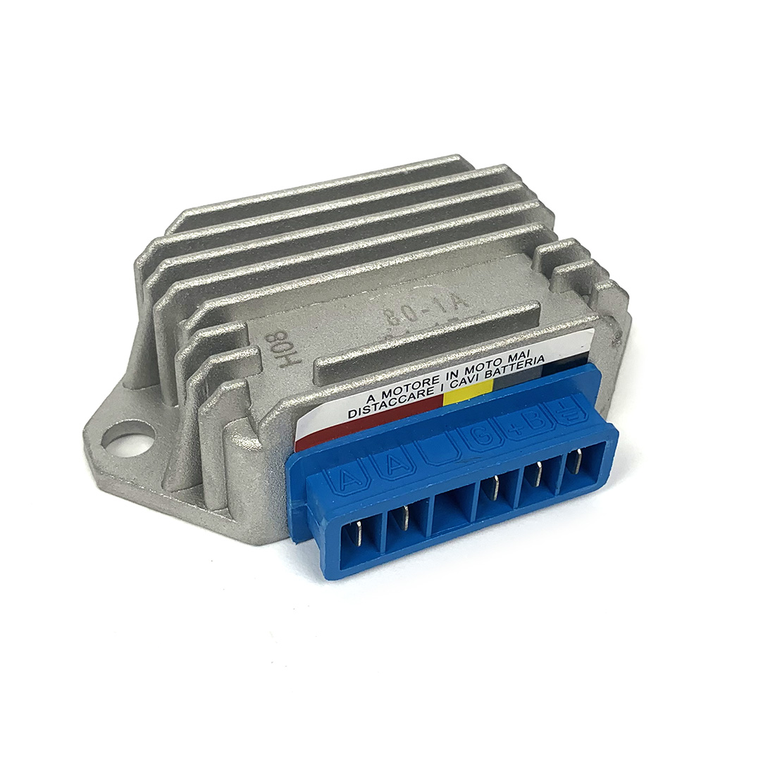
Regulator Rectifier 12 Volt 5 Pole AC/DC VSX VLX PX Stella
Areyourshop Regulator Rectifier Voltage Fit For Suzuki GN125 ...

Regulator Rectifier Voltage Regulator 11 Pole 5 Wire GY6 125 ...
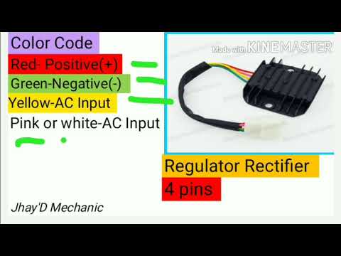
4 wire / 5 wire regulator rectifier wiring diagram and Explain Regulator (TAGALOG)

Motorcycle Electrical System Dropshipping Wholesaler ...
ATV VOLTAGE REGULATOR RECTIFIER TAOTAO 200CC 250CC 5 WIRES VR16
Regulator /Rectifier and some wiring -
0 Response to "36 5 wire regulator rectifier wiring diagram"
Post a Comment