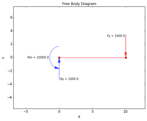
36 beam free body diagram
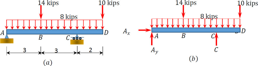
Example 4 - Aerospace Engineering Free-Body Diagram of Beam:The beam is supported by a pin at point A and a horizontal roller at point D. Therefore, there are two unknown reactions at point A and one at point D as shown below. Notice that in drawing the free-body diagram we assume a direction for each reaction load. Answered: Which of the following free body… | bartleby Which of the following free body diagrams correctly represents the highlighted beam given a 100 psf area load on the floor plan shown. [NOTE: There is no framing beyond that shown in the image.] 500 lb/ft 30 ft- OPTION A 15 ft- 1,875 lb| 500 lb/ft OPEN OPTION B DECK SPAN, TYP 1,875 lb OPTION C 250 lb/ft OPTION D Option A Option B O Option C Option D 20 ft
Beam Calculations Made Easy - From Free Body to Stress ... Once you have your loads, create a free body diagram showing each load and where it occurs on the beam. It doesn't have to be exactly to scale, but it helps if it is close. Be sure to leave room directly below the beam so that we can draw our shear-moment diagram!
Beam free body diagram
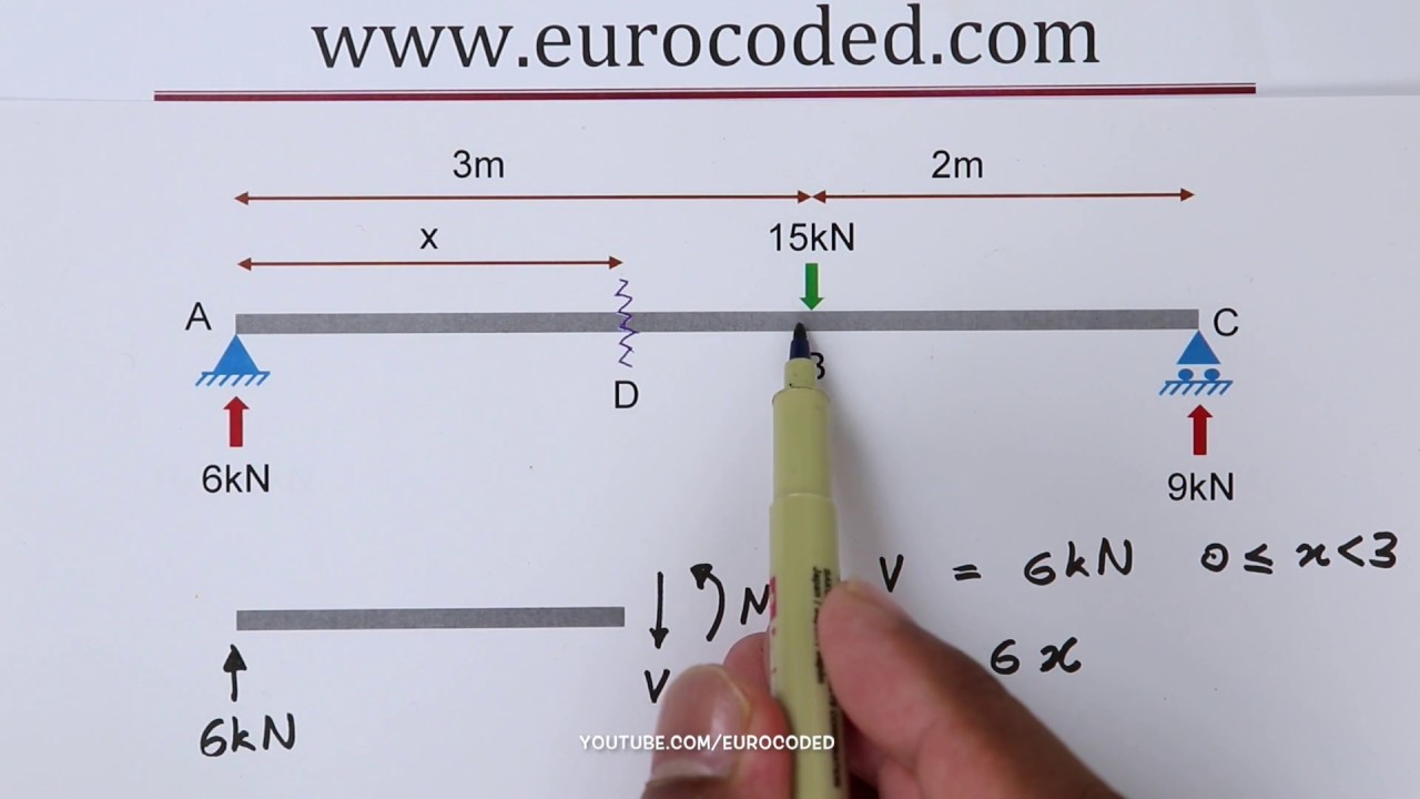
Transcribed image text : Problem 3 A simply supported beam ... All the dimensions are given in the figure, and the weight of the beam is neglected. (a) Draw the free body diagram for the beam, showing all the applied forces, moments and reaction forces. (b) Use the equations of equilibrium to find the reaction forces at A and C. P 15 kN MD 10 kNm K >K >K 켜 6 m. Mechanics Map - Shear and Moment Diagrams A free body diagram of a beam is shown above the shear and moment diagrams for that beam. Positive and negative internal bending moments. To read the plot, you simply need to take the find the location of interest from the free body diagram above, and read the corresponding value on the y-axis from your plot. Lecture 23: Cantilever Free Body Diagram Example ... The video, then, displays a cantilever beam subjected to a point load of 20 N at free edge of the beam in downward direction. The length of the beam has given as 3 m. Next, using the given information, the video shows how to draw the FBD illustrating what reactions and momentum have been caused by the fixed support.
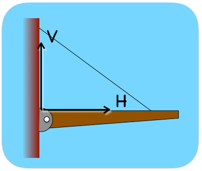
Beam free body diagram. How to Calculate Bending Moment Diagram? - SkyCiv Once you have the reactions, draw your Free Body Diagram and Shear Force Diagram underneath the beam. Finally calculating the moments can be done in the following steps: 2. From left to right, make "cuts" before and after each reaction/load To calculate the bending moment of a beam, we must work in the same way we did for the Shear Force Diagram. The man stands at the center of the plank. The planes ... Draw the free-body diagram for the beam. A is a roller and B is a pin Draw the vectors starting at the black dots. The location and orientation of the vectors will be graded. The length of the vectors will not be graded. No elements selected Select the elements from the list and add them to the canvas setting the appropriate attnbutes. Example 6 - Aerospace Engineering Free-Body Diagram of Beam:The beam is fixed at point A. Therefore, there are two reaction forces and one reaction moment at this point as shown below. We assume a direction for each reaction load. Also to simplify the calculations, the distributed force is represented by its resultant acting at its centroid., PDF Structural Analysis by Hand - VBCOA Free Body Diagram Joist 66.67 plf 10'-0" Beam 350 plf 12'-0" w l RR 32 Example: Free Body Diagram On plans provided, first floor joist adjacent fireplace hearth extension: 15'-4" 33 You Try It Draw the free body diagram of the sunroom beam Show load and its value Total uniform load = 50 psf
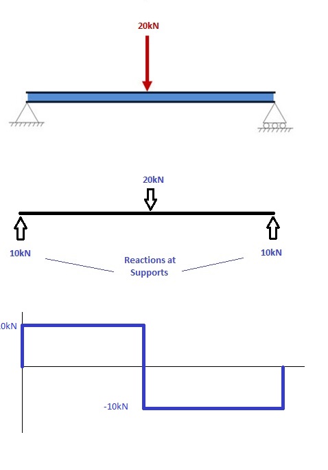
PDF ENGR-1100 Introduction to Engineering Analysis FREE-BODY DIAGRAMS (Section 5.2) 2. Show all the external forces and couple moments. These typically include: a) applied loads, b) support reactions, and, c) the weight of the body. Idealized model Free-body diagram (FBD) 1. Draw an outlined shape. Imagine the body to be isolated or cut "free" from its constraints and draw its outlined shape. Free Online Beam Calculator | SkyCiv Engineering Free online beam calculator for generating the reactions, calculating the deflection of a steel or wood beam, drawing the shear and moment diagrams for the beam. This is the free version of our full SkyCiv Beam Software. This can be accessed under any of our Paid Accounts, which also includes a full structural analysis software. Simply Supported Beam | It's Complete Overview with 2 cases Case I: For Simply supported Beam with a concentrated load F acting at the center of the Beam. Below is a free body diagram for a simply supported steel beam carrying a concentrated load (F) = 90 kN acting at the Point C. Now compute slope at the point A and maximum deflection. if I = 922 centimer 4, E = 210 GigaPascal, L =10 meter. Simply Supported Beams Free Body Diagram Example | Statics ... for more FREE video tutorials covering Engineering Mechanics (Statics & Dynamics)The objectives of this video are to give an introducto...
Lecture 24: Advanced Free Body Diagram Beam Example ... The beam is subjected to two different loads i.e., a point load of 30 KN acting downward at 2 m away from right end and a uniformly distributed load of 5 KN/m acting downward and over 2 m length of the beam from right end. All the necessary dimensions are also given. Moving on, the video draws the free body diagram for the problem at first step ... PDF Free Body Diagrams - Memphis 33 Free Body Diagrams Wednesday, October 3, 2012 New Support Conditions Pin Connection ! The next type of connection is the pin or the smooth pin or hinge ! One way to think of this is to drive a nail through a ruler partway into a table top 34 Free Body Diagrams Wednesday, October 3, 2012 New Support Conditions Pin Connection ! PDF 3. BEAMS: STRAIN, STRESS, DEFLECTIONS The beam, or ... A free body diagram of the portion of the beam between the left end and plane a-a is shown in Fig. 3.3. A study of this section diagram reveals that a transverse force Vrand a couple Mrat the cut section and a force, R, (a reaction) at the left support are needed to maintain equilibrium. Beam Reactions and Diagrams - Strength of Materials ... Draw the beam free body diagram Replace the uniform distributed load (if any) with the equivalent point load Solve ΣM A = 0 (sum of moments about support A). This will give you R B (reaction at support B). Solve ΣM B = 0. This will give you R A. Using R A and R B found at steps 3 and 4 check if ΣV = 0 (sum of all vertical forces) is satisfied.
Shear Force And Bending diagrams - Roy Mech
PDF 7.4.1 The Beam - idc-online.com The moments and forces acting within the beam can be evaluated by taking free-body diagrams of sections of the beam. There are clearly two distinct regions in this beam, to the left and right of the load. Fig. 7.4.8a shows an arbitrary portion of beam representing the left-hand side. A coordinate system has been introduced, with x measured from A.3
Chap. 2 Force Vectors
PDF Unit M4 - Massachusetts Institute of Technology Figure M4.3-7 Geometry and free body diagram of indeterminate beam main beam house walls concrete wall concrete lally wall columns ~ ~ ~ ~ ~ ~ ~ F F ~ ~ ~ ~ ~ FREE BODY DIAGRAM:--> We will save looking at the statically indeterminate case for a later unit. Let's start off by considering….
Free body diagram of pin support and cable | Physics Forums
PDF BEAM DIAGRAMS AND FORMULAS - Arch Exam Academy beam diagrams and formulas by waterman 55 1. simple beam-uniformly distributed load 2. simple beam-load increasing uniformly to one end ... 23. beam fixed at one end, free to deflect vertically but not rotate at other-concentrated load at deflected end 24. beam overhanging one support-uniformly distributed load. 25. beam overhanging one support ...

From the beam shown below, i) Draw the Free Body Diagram (FBD ...
What are Free Body Diagrams? - Massachusetts Institute of ... diagram (FBD). A free body diagram is a graphic, dematerialized, symbolic representation of the body (structure, element or segment of an element) in which all connecting "pieces" have been removed. A FBD is a convenient method to model the structure, structural element, or segment
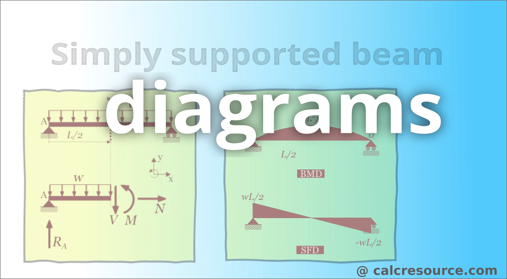
Simply supported beam diagrams : article | calcresource
Free Beam Calculator - Optimal Beam Free Beam Calculator for Statically Indeterminate Beams. Support Reactions. Shear Diagram. Moment Diagram. Indeterminate / Continuous Beams. Premium: Deflection and Stress Diagrams. Premium: Custom and Standard Sections or Materials. Premium: Save Unlimited Models and Sections. Premium: PDF Reports and Custom Logo.
6161103 5.2 free body diagrams
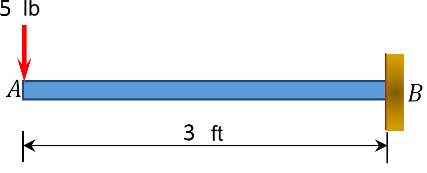
Lecture 23: Cantilever Free Body Diagram Example ... The video, then, displays a cantilever beam subjected to a point load of 20 N at free edge of the beam in downward direction. The length of the beam has given as 3 m. Next, using the given information, the video shows how to draw the FBD illustrating what reactions and momentum have been caused by the fixed support.

Statics: Free Body Diagrams
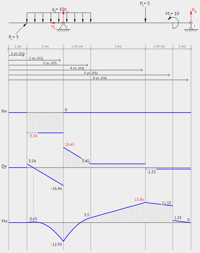
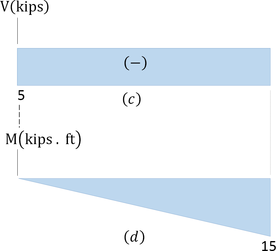
Mechanics Map - Shear and Moment Diagrams A free body diagram of a beam is shown above the shear and moment diagrams for that beam. Positive and negative internal bending moments. To read the plot, you simply need to take the find the location of interest from the free body diagram above, and read the corresponding value on the y-axis from your plot.
Free body diagrams
Transcribed image text : Problem 3 A simply supported beam ... All the dimensions are given in the figure, and the weight of the beam is neglected. (a) Draw the free body diagram for the beam, showing all the applied forces, moments and reaction forces. (b) Use the equations of equilibrium to find the reaction forces at A and C. P 15 kN MD 10 kNm K >K >K 켜 6 m.

Solved) - To understand now to draw the free-body diagram of ...

Example 1
Untitled

Green Mechanic: Shear Force in a Beam Lab Report

Compound Beams: Structural Analysis — Engineering — WeTheStudy
2D Finite Element Analysis - Validation | MechaniCalc
classical mechanics - How do I make free body diagram for ...
Free Body Diagram for simply supported beam | Physics Forums
Shear force and Bending Moment diagram for cantilever
Determining the Shear Force and Bending Moment Equations of ...
Example 4

Shear and moment diagram - Wikipedia
Extended Free Body Diagrams
1.4: Internal Forces in Beams and Frames - Engineering LibreTexts

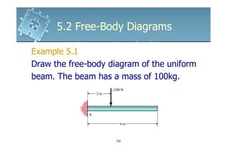
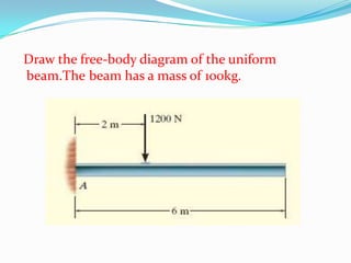
Ch4.1.pdf - 5.2 FREE-BODY DIAGRAMS 207 EXAMPLE 5.1 Draw the ...

Beam Free Body Diagram Calculator | Bending Moment and Shear ...
6.2 Shear/Moment Diagrams – Engineering Mechanics: Statics

Statics eBook: Shear and Moment Diagrams I
6.2 Shear/Moment Diagrams – Engineering Mechanics: Statics
draw the free body diagram for the following problems a the cantilevered beam in prob 5 10 b the b 2

Draw a free-body diagram of the beam. | Study.com
Strategy: Interpreting Beam Resultant Forces and Moments
How to Calculate Bending Moment Diagram? | SkyCiv
What is the best way to draw a free body diagram and a shear ...

a) Draw the free-body diagram of the beam. (b) Determine the ...
What are Free Body Diagrams?

a) Draw the free-body diagram for the steel beam with applied ...
How to Draw a Free Body Diagram - Simply Supported Beam with ...
0 Response to "36 beam free body diagram"
Post a Comment