36 pv diagram practice problems
Solution: The engine shown in the followin ... - Clutch Prep Our tutors have indicated that to solve this problem you will need to apply the Heat Engines & PV Diagrams concept. You can view video lessons to learn Heat Engines & PV Diagrams Or if you need more Heat Engines & PV Diagrams practice, you can also practice Heat Engines & PV Diagrams practice problems . Concepts of Managerial Economics (With Diagram) Where PV = present value and . i = rate of interest . As a cross check one may multiply the PV of Rs. 95.24 by 1.05 to determine how much money will have accumulated during the year at 5%. The answer is Rs. 95.24 x 1.05 = Rs.100. In other words, Rs. 95.24 plus the interest on it will accumulate to an amount exactly equal to Rs. 100.
PDF Practice Thermodynamics Problems Practice Thermodynamics Problems 1. A gas is initially at temperature T 0 and pressure P 0. If the gas undergoes an isothermal expansion to ... The path of an irreversible process cannot be traced on a PV diagram. C)Melting an ice cube in a cup of room temperature water is an example of this kind of process. D)Macroscopic quantities like ...

Pv diagram practice problems
PDF Lecture 3 Examples and Problems - University of Illinois ... Examples and Problems Reading: Elements Ch. 1-3. Physics 213: Lecture 3, Pg 2 ... Lecture 3, p 3 For an ideal gas at constant T, p is inversely proportional to the volume. Ideal Gas p-V, p-T Diagrams NkT p V = increasing T Volume Pressure p vs V at various constant T's 0 Pressure Temperature 0 Pressure →zero as ... pV γ= constant ... Solar One Line Diagram 101: For Solar Contractors 24.9.2019 · A one-line diagram provides a core breakdown of a solar PV design, presented in a straightforward, easy-to-digest format. First and foremost, the diagram shows all the primary electrical components. This includes solar panels , inverters, disconnect switches, sub-panels, and junction boxes. (PDF) Chemical Engineering Design Principles Practice and ... Chemical Engineering Design Principles Practice and Economics of-Plant and Process Design . × Close Log In. Log in with Facebook Log in with Google. or. Email. Password. Remember me on this computer. or reset password. Enter the email address you signed up with and we'll email you a reset ...
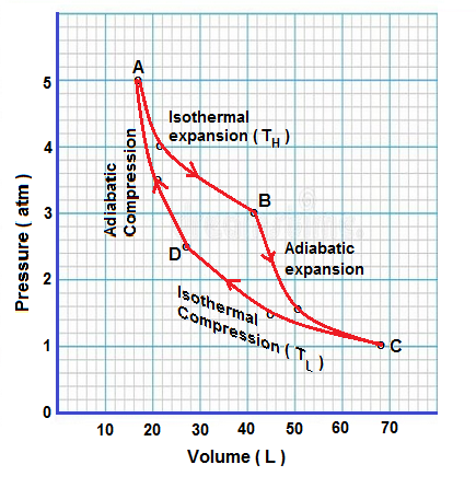
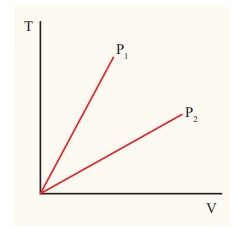
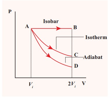
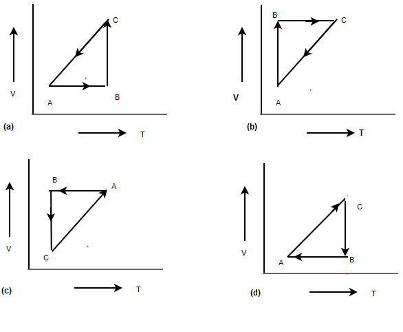
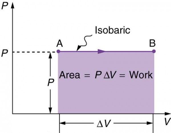
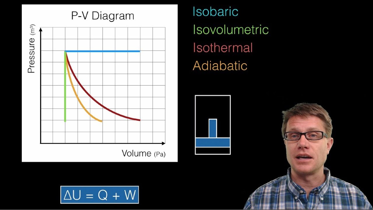
Pv diagram practice problems. AP Physics 2 Review Problems Data is obtained from a PV Diagram. YouTube video describing the problem; Efficiency of Engine: Determine the efficiency of an engine (0 - 1) based on the energy flow that is presented to you. YouTube video describing the problem; Efficiency of Engine Based on PV Diagram: Determine the efficiency of an engine (0 - 1) based on the PV Diagram ... PDF Isothermal process on p V T V, and p T diagrams ideal gas law: pV = nRT Consider the p-V diagram below in which the system evolves from a → b → c. If T 0 ~ 240K (and thus RT 0 = 2,000 J mol-1), how many moles of gas, n, are in the system? a) 5 b) 105 c) 50 d) 1,000 e) Not enough information to tell n = = = 50 pV RT 0 100,000 2,000 isotherm isobar isochor Diagrams of Thermodynamic Cycles — Collection of Solved ... The VT diagram shows: In the segment AB the volume of the gas is directly proportional to the temperature. This means that in this phase the pressure is constant, it is an isobaric process. In the pV diagram it is represented by a horizontal line. We can see that the volume in the first phase (from A to B) increases. Thermodynamics, PV Diagrams, Internal Energy, Heat, Work ... This physics video tutorial explains the concept of the first law of thermodynamics. It shows you how to solve problems associated with PV diagrams, interna...
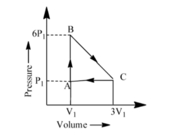
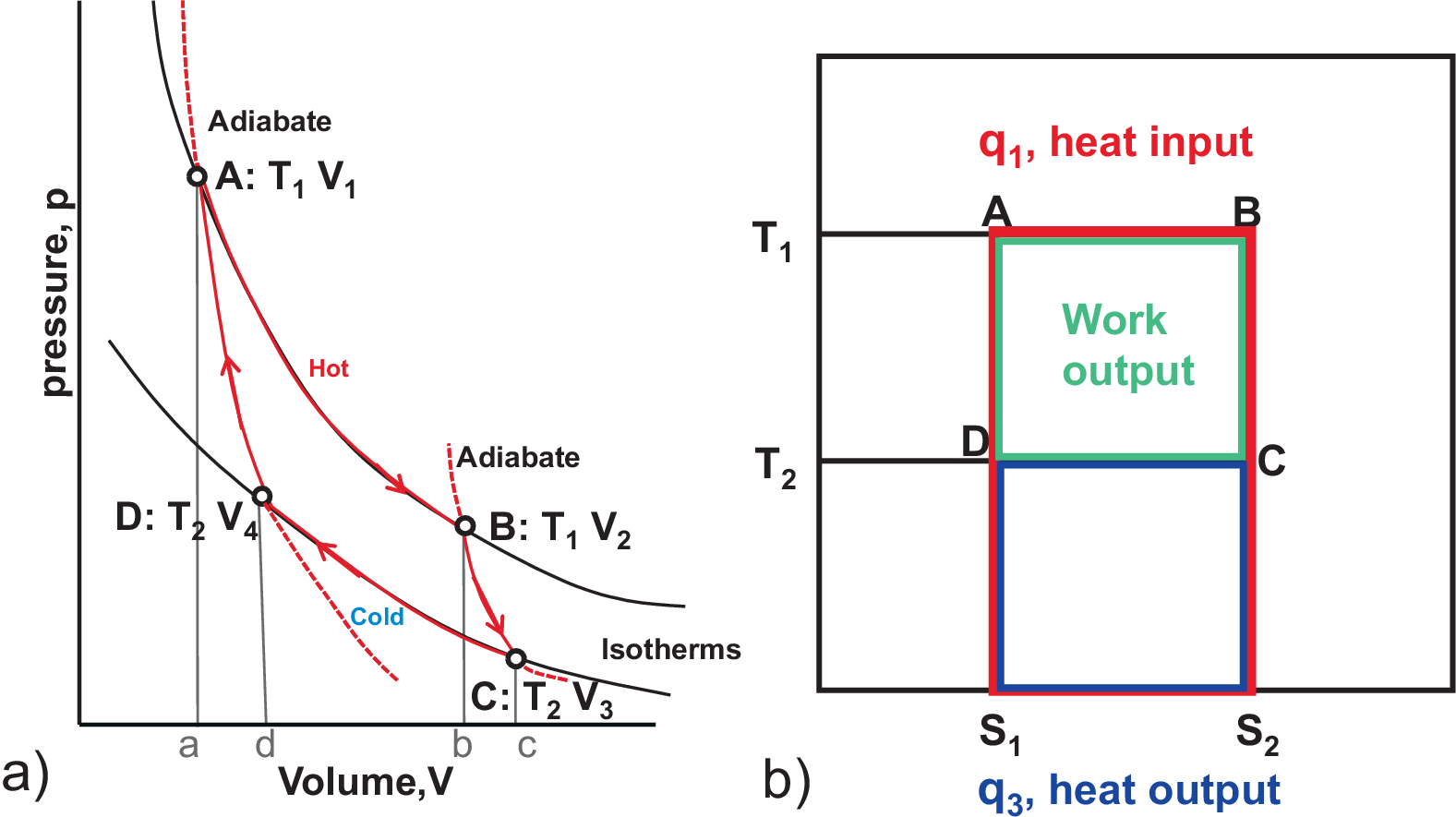
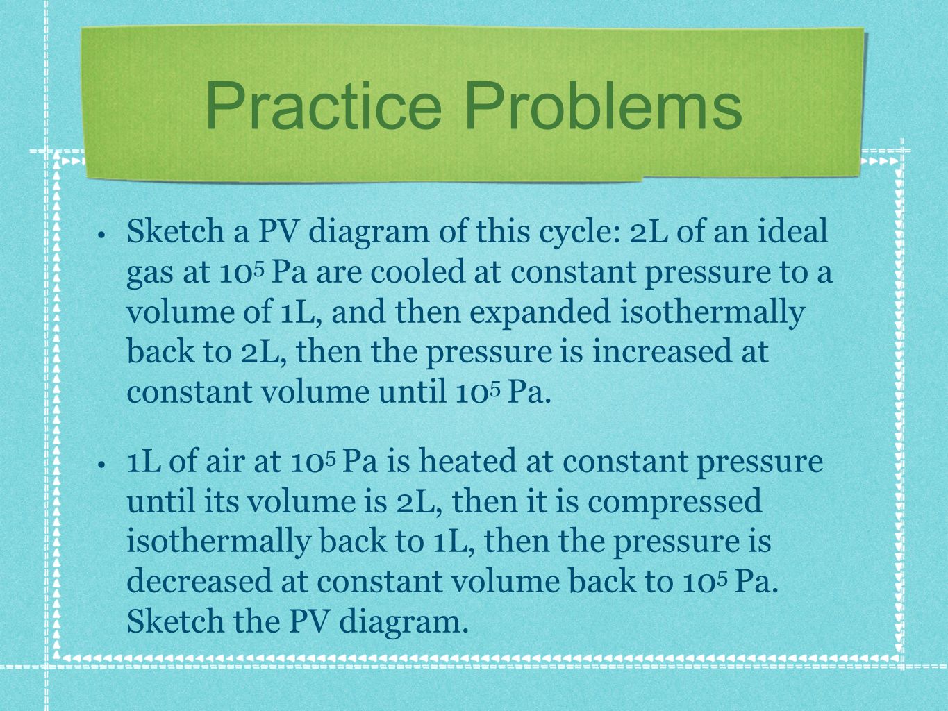
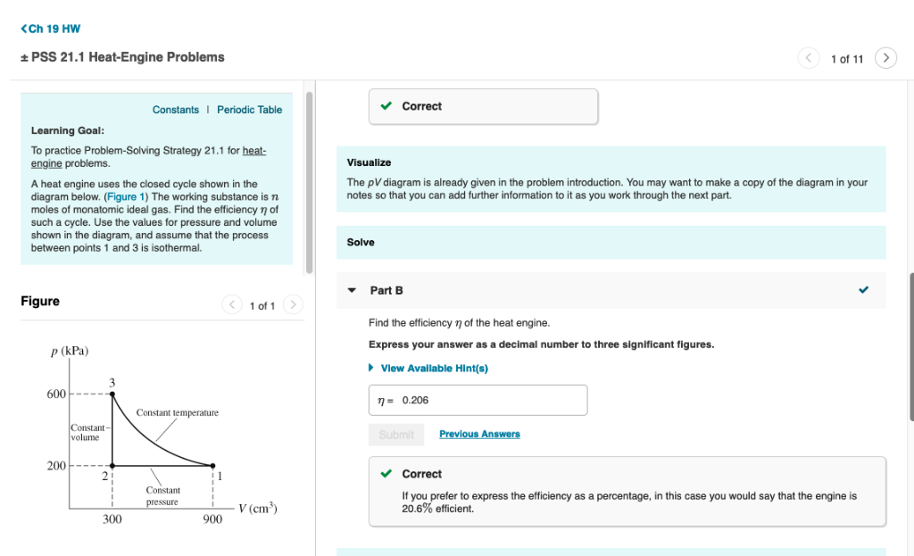
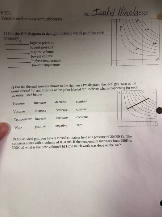
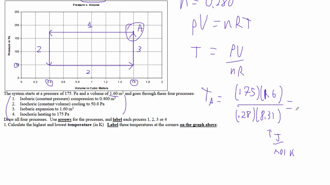
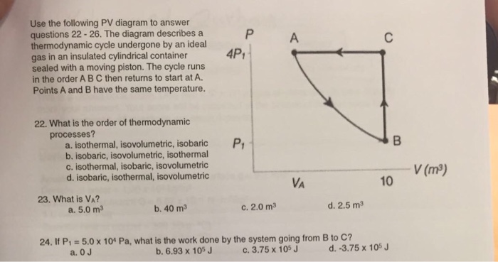
PDF Final Exam Practice Answers - Ursinus College The PV diagram for a heat engine is shown above. The cycle consists of two constant volume and two constant pressure processes. The pressure and volume at point a are Pa = 3.0×10⁵ Pa and Va = 6.0×10⁻³ m3. Thepressureandvolume at point c are Pc = 6.0×10⁵ Pa andVc = 2.0×10⁻³ m3. General formalism for calculating the thermal efficiency ... 17.2.2022 · We develop a general method for calculating the thermal efficiency of arbitrary thermodynamic cycles defined in the pressure-volume (p–V) diagram.To demonstrate how effective our approach is, we calculate the thermal efficiency of ideal gas engines for a few non-trivial cycles in the p–V diagram, including a circular shape, a heart shape, a cycloid of Ceva, … [Solved] III. INTERPRETING PV DIAGRAMS The PV diagram ... III. INTERPRETING PV DIAGRAMS The PV diagram below shows the state of an ideal gas is being changed from position 1 to position 2. What is the change in the internal energy of the gas during this process? (A) AU = W (B) AU = Q (C) AU > 0 (D) AU = 0 (E) AU PDF 1) Use the P-V diagram below to answer the following questions Practice Problems, Chapters 1 - 4 1. Use the P-V diagram below to answer the following questions 1a) The Net Work for the cyclic process is: a) Zero b) Positive c) Negative d) Cannot tell from the diagram 1b) The processes from states 1 to 2 and 3 to 4 are: a) Isothermal b) Isobaric c) Isochoric d) Isometric Which of the following process is correct for given P - V ... One mole of an ideal diatomic gas is taken through the cycle as shown in the figure1 2 : isochoric process2 3 : straight line on P-V diagram3 1 : isobaric process The average molecular speed of the gas in the states 1, 2 and 3 are in the ratio. P − V diagram of an ideal gas for a process A B C is as shown in the figure. The pV diagram is already given in the problem | Chegg.com The pV diagram is already given in the problem introduction. You may want to make a copy of the diag work through the next part. Learning Goal: To practice Problem-Solving Strategy 21.1 for heat-engine problems. A heat engine uses the closed cycle shown in the diagram below. (Figure 1) The working substance is n moles of monatomic ideal gas. Thermodynamics questions (practice) - Khan Academy Practice: Thermodynamics questions. This is the currently selected item. ... First law of thermodynamics problem solving. PV diagrams - part 1: Work and isobaric processes. PV diagrams - part 2: Isothermal, isometric, adiabatic processes. Second law of thermodynamics. 1st law Ch2, Lesson C, Page 21 - Homework Problems Sketch a PV Diagram and a TV Diagram for ammonia and plot the 5 points from parts (a) through (e) on each diagram. Do not make your diagram to scale, just make sure each point lies in the proper region.Be sure to show and label relevant isobars and isotherms. Keep in mind that thermodynamic data from tables are not exactly the same. show four steps of carnot engine in p v graph write the ... Mechanical Engineering Problems With Solution - DocShare.tips 22 / Problems and Solutions in Mechanical Engineering with Concept Q. 35: A mass of 1.5kg of air is compressed in a quasi static process from 0.1Mpa to 0.7Mpa for which PV = constant. The initial density of air is 1.16kg/m3. Solved Example Problems for Thermodynamic Processes PDF Thermodynamic systems - Northeastern University pV γ=constant =1 1 =constant pV γ pVγ 1 constant 2 2 1 1 1 = = T Vγ− T V γ− pV =nRT During an adiabatic expansion process, the reduction of the internal energy is used by the system to do work on the environment. During an adiabatic compression process, the environment does work on the system and increases the internal energy. An ideal gas is taken around the cycle ABCA as shown class 11 ... The Cardiac Cycle & PV Loops - Tulane University The figure below shows pressure volume loops taken from Patient #3 when at rest (black diagram), and after being given a cardiovascular drug (red diagram). Which type of drug would most likely produce the change indicated by the red diagram? ... which results in the PV loop indicated in red. The PV loop indicated in black was taken prior to the ... P-V Diagram Problems and Solutions Pressure-Volume Diagrams - Problems - The Physics ... Problems practice One mole of an ideal, monatomic gas runs through a four step cycle. All processes are either isobaric or isochoric. The pressure and volume of the gas at the extreme points in the cycle are given in the table below. Sketch the PV graph of this cycle. Determine the temperature at state A, B, C, and D. PV Diagrams & Work - Physics Video | Clutch Prep PDF Lesson 42c: PV Diagrams - Studyphysics look at PV diagrams. A PV diagram is a graph of Pressure as a function of Volume. There are four different situations that you can expect to see shown in PV diagrams: 1. Isobaric: the gas is held at a constant pressure 2. Isochoric: the gas is held at a constant volume 3. Isothermal: the gas is held at a constant temperature 4. Solved Example Problems for Thermodynamic Processes Isothermal thermodynamic processes - problems and ... 1. PV diagram below shows an ideal gas undergoes an isothermal process. Calculate the work is done by the gas in the process AB. Solution Work done by a gas is equal to the area under the PV curve AB = triangle area + rectangle area W = [½ (8 x 10⁵-4 x 10⁵)(3-1)] + Pv Diagram Work Done Area Under Or Enclosed By Curve - Energy ... Problem 1What is PV Diagram 2 What is the meaning of work ... 7 II. Guided Practice Activity Activity No.2 (Interpret a PV diagram) Offline activity Problem: How to interpret a PV diagram? Hypothesis: In interpreting a PV diagram. Remember this, if a gas is compressed, the volume decrease, and the work done is POSITIVE +. If gas is expanding, the volume increases, and the work done is NEGATIVE. Materials: Paper, ballpen and calculator Procedure: 1. Diagrams of Thermodynamic Cycles — Collection of Solved Problems HP 12c Financial Calculator - Basic Loan Calculations | HP ... Practice solving loan problems Example 1 To help sell used cars, a car dealer offers loans with a 10.5% annual percent rate compounded monthly with terms up … Solved Example Problems for Thermodynamics Cyclic processes (Pdf) Practice Problems for Engineering Thermodynamics This book includes practice problems for Engineering Thermodynamics course. ... Sketch the process on P-V diagram and determine the total work transfer. ... Process 1-2: compression with PV ... Carnot cycle: p-V diagram and T-S diagram PROBLEM SOLVING STRATEGY 21 1 Heal-engine problems | Chegg.com Question: PROBLEM SOLVING STRATEGY 21 1 Heal-engine problems MODEL: Identify each process in the cycle, VISUALIZE: Draw the pV diagram of the cycle. Learning Goal: To practice Problem-solving Strategy 21 1 for heat engine problems A heal engine uses the closed cycle shown in the diagram below. (Eiguro 1) The working substance is n moles of ... The molar heat capacity of a monoatomic gas is: What are PV diagrams? (article) - Khan Academy A convenient way to visualize these changes in the pressure and volume is by using a Pressure Volume diagram or PV diagram for short. Each point on a PV diagram corresponds to a different state of the gas. The pressure is given on the vertical axis and the volume is given on the horizontal axis, as seen below. Lesson 5 Introduction to Entropy Liceo Da Procida. - ppt download Solved Example Problems for Thermodynamic Processes The PV diagrams for a thermodynamical system is given in the figure below. Calculate the total work done in each of the cyclic processes shown. Solution. In the case (a) the closed curve is anticlockwise. So the net work done is negative, implying that the work done on the system is greater than the work done by the system. Solved Ch 19 HW + PSS 21.1 Heat-Engine Problems 1 of 11 ... PV - diagram of a mono atomic ideal gas is a line passing ... PV- diagram of a mono atomic ideal gas is a line passing through origin. Find the molar heat capacity in the process . ... Problem solving tips > Diagram set > Cheatsheets > Common Misconceptions > Practice more questions . JEE Mains Questions. 8 Qs > JEE Advanced Questions. 3 Qs > NEET Questions. 4 Qs > AIIMS Questions. 6 Qs > Solved P 255 Practice on thermodynamic processes Name Izabel ... Pressure-Volume Diagrams - The Physics Hypertextbook PV diagram is a "steep hyperbola" Q = 0 ⇒ ∆ U = W PVγ = constant Superman saves the day with adiabatic cooling. The rapid expansion of the gas expelled from Superman's lungs cooled the overheating truck, thwarting the evil General Zod's attempt to explode its fuel tank. Thank you Superman. … and the rest liquids solids What are PV diagrams? (article) | Khan Academy Work & PV Diagrams Video & Text Solutions For College ... Work & PV Diagrams. Q. Work Done by the Lungs. The graph (Figure 1) shows a pV-diagram of the air in a human lung when a person is inhaling and then exhaling a deep breat... Solved • Jul 14, 2020. Work & PV Diagrams. Q. A) Find w12, the work done on the gas as it expands from state 1 to state 2.Express the work done in terms of Po and VoB ... The pressure-volume (pV) diagram and how work is produced in ... (PDF) THERMODYNAMICS PROBLEMS.pdf | Yuri G ... - Academia.edu Processes (Ideal Gas) A steady flow compressor handles 113.3 m 3 /min of nitrogen (M = 28; k = 1.399) measured at intake where P1= 97 KPa and T1= 27 C. Discharge is at 311 KPa. The changes in KE and PE are negligible. For each of the following P-V Diagram Problems and Solutions (PDF) Chemical Engineering Design Principles Practice and ... Chemical Engineering Design Principles Practice and Economics of-Plant and Process Design . × Close Log In. Log in with Facebook Log in with Google. or. Email. Password. Remember me on this computer. or reset password. Enter the email address you signed up with and we'll email you a reset ... Isothermal thermodynamic processes – problems and solutions ... Solar One Line Diagram 101: For Solar Contractors 24.9.2019 · A one-line diagram provides a core breakdown of a solar PV design, presented in a straightforward, easy-to-digest format. First and foremost, the diagram shows all the primary electrical components. This includes solar panels , inverters, disconnect switches, sub-panels, and junction boxes. P - V diagram of an ideal gas is shown in figure. Work done ... PDF Lecture 3 Examples and Problems - University of Illinois ... Examples and Problems Reading: Elements Ch. 1-3. Physics 213: Lecture 3, Pg 2 ... Lecture 3, p 3 For an ideal gas at constant T, p is inversely proportional to the volume. Ideal Gas p-V, p-T Diagrams NkT p V = increasing T Volume Pressure p vs V at various constant T's 0 Pressure Temperature 0 Pressure →zero as ... pV γ= constant ... The First Law of Thermodynamics and Some Simple Processes ... TuHSPhysics - IB A15.1 PV Diagrams and Work What are PV diagrams? (article) | Khan Academy P-V Diagram Problems and Solutions Thermodynamics and P-V Diagrams P-V Diagram Problems and Solutions Module Price Index – pv magazine International Chapter 3 | Thermodynamics Solved Use the following PV diagram to answer questions ... The First Law of Thermodynamics Ideal Gas Processes - ppt ... the p v diagram for a cyclic process is a triangle abc drawn ... An example of a problem in which students are asked about the ... The above P - V diagram represents the thermodynamic cycle of ... 02-Thermodynamic-process-Practice-Problem P-V Diagram Problems and Solutions How to solve PV diagrams example problem FULLY-WORKED / adiabatic process / isothermal process


0 Response to "36 pv diagram practice problems"
Post a Comment