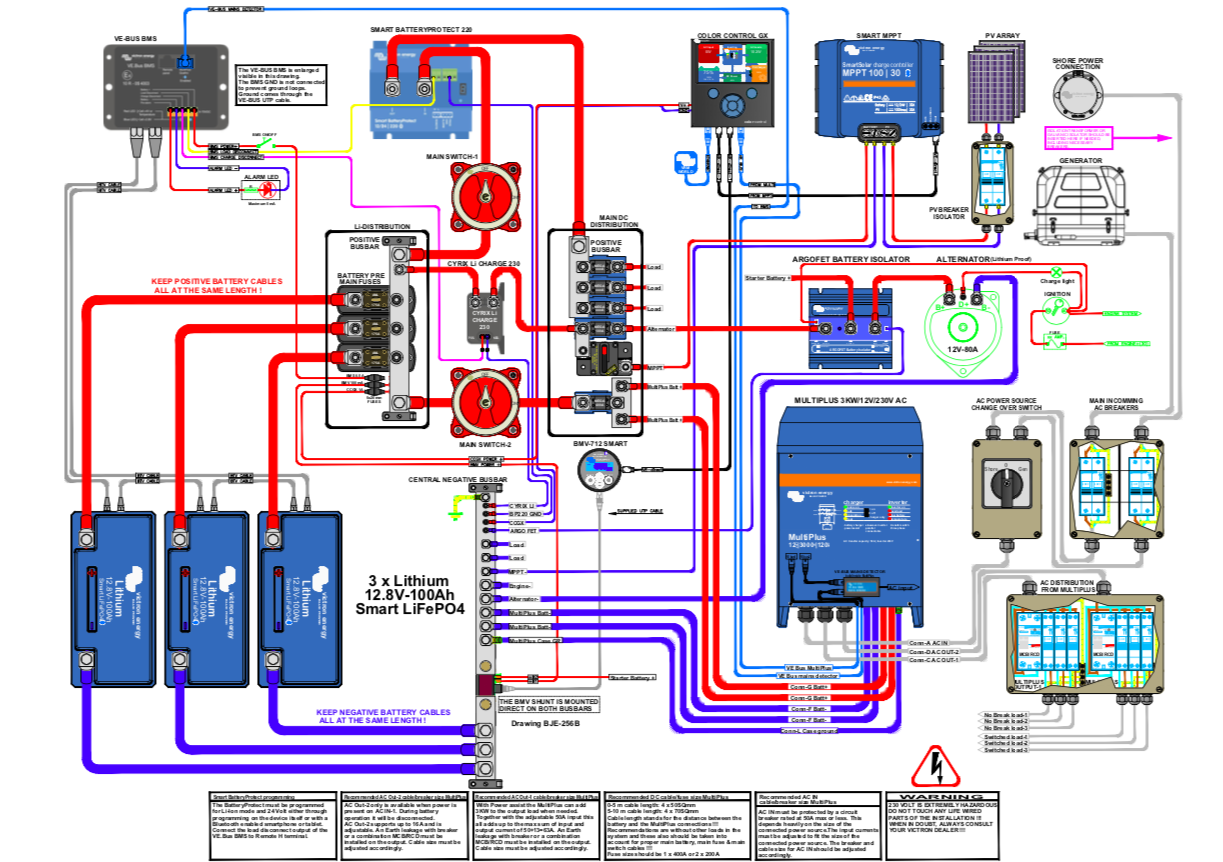
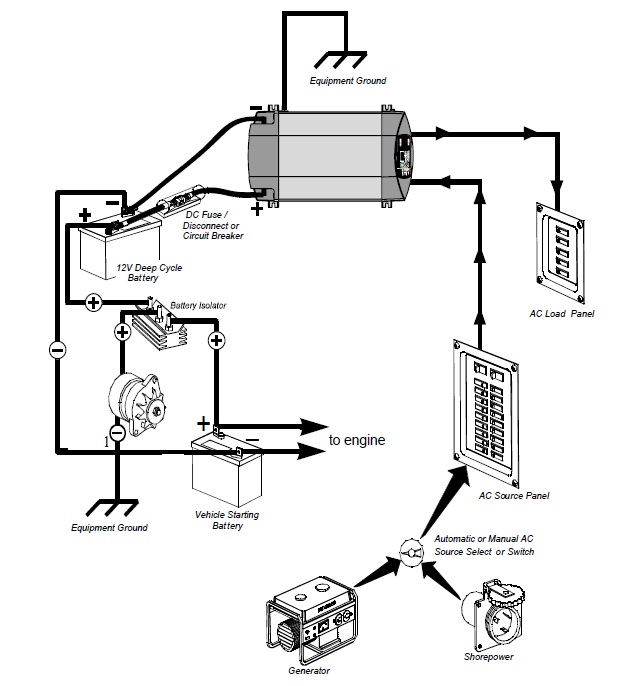
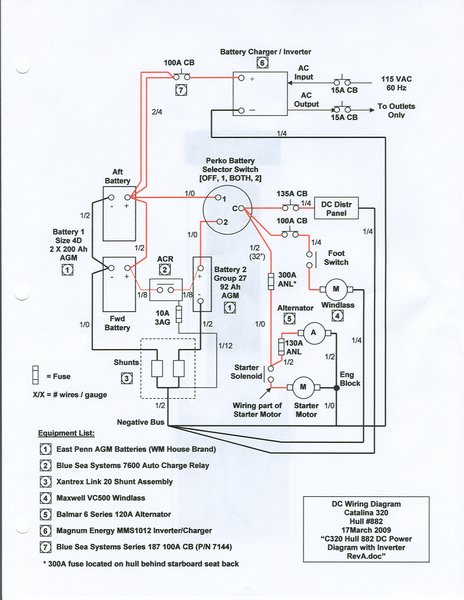
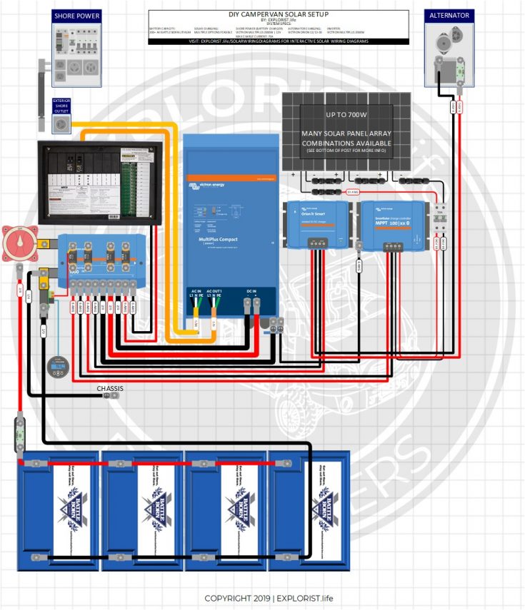
37 marine inverter wiring diagram
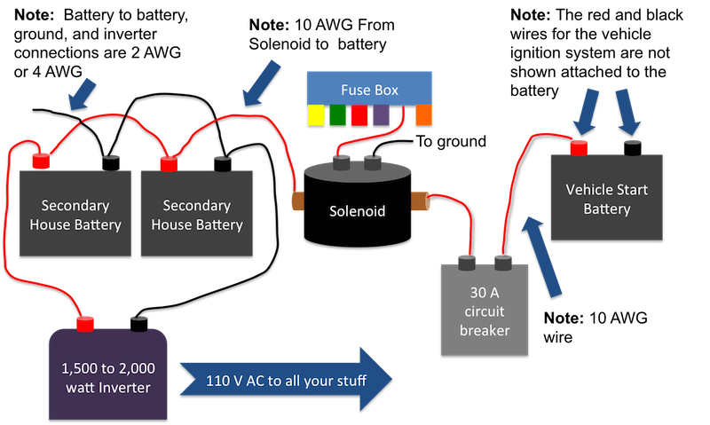
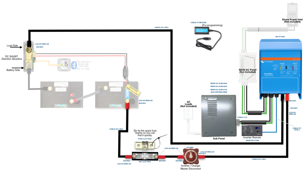
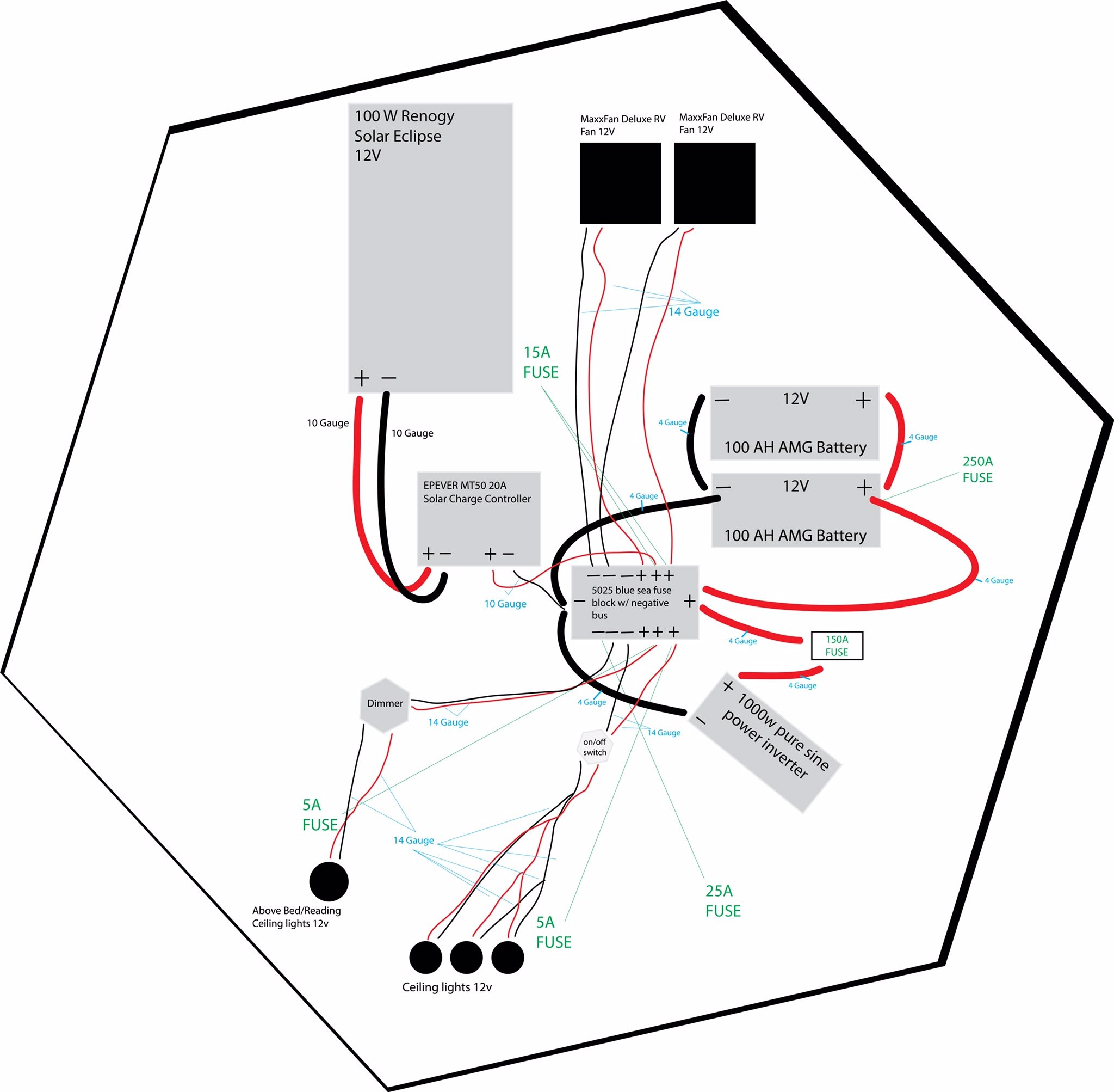
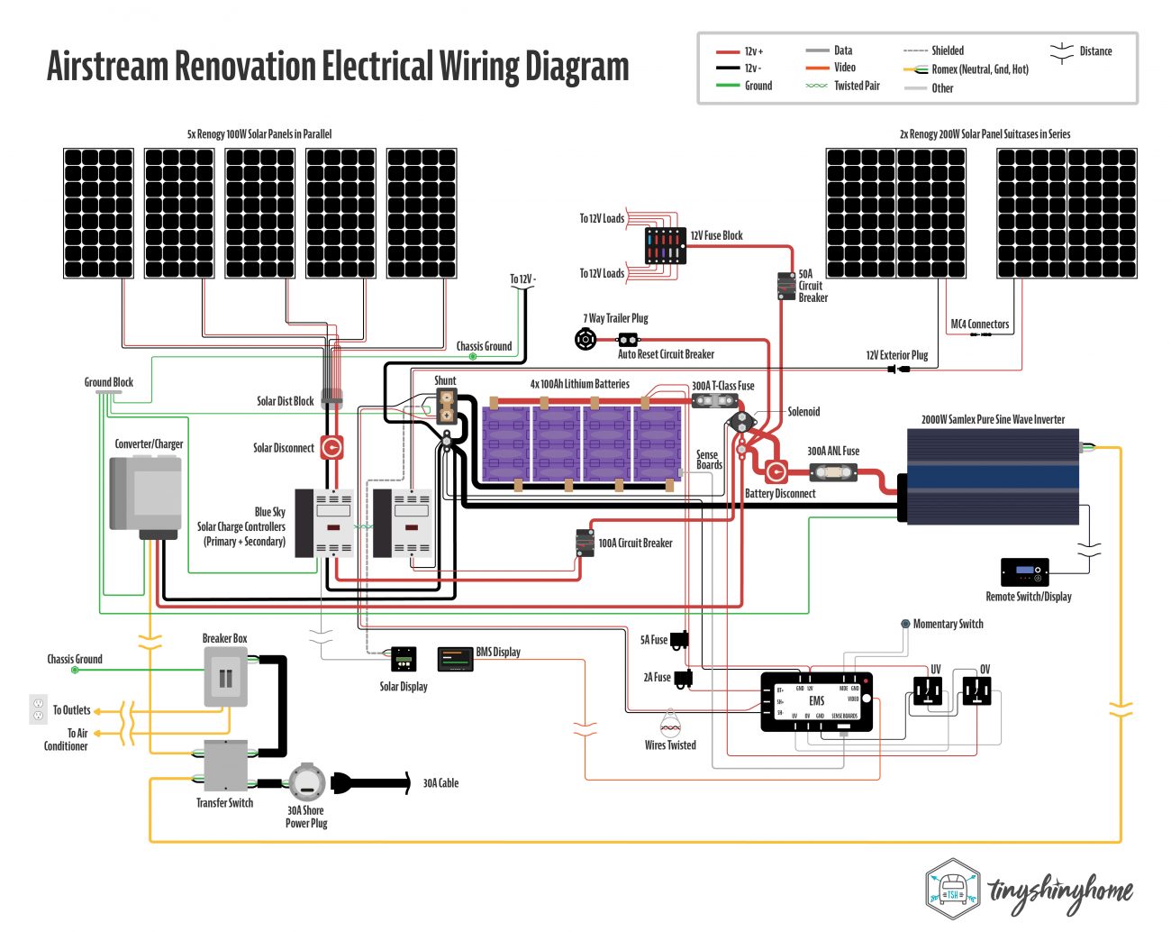
rv inverter wiring schematic - IOT Wiring Diagram Rv Inverter Wiring Schematic. By IOT | August 23, 2015. 0 Comment. Rv inverter wiring diagram electricity explained justdownsize 12 volt dc 120 ac battery install four diffe diy methods to get off the grid 30a oem solar retrofit explorist life multiplus schematic vintage travel trailer victron community last updated 2000w 200 400ah lithium 700w ... Benefits of Installing an Inverter Bypass Switch - Waggoner The photos below show two versions of the bypass switch. It can be installed anywhere but is most economical when next to the inverter. The switch on the left uses a pair of interlocking circuit breakers to bypass the inverter. The rotary switch on the right does the same thing with a single move. Arthur Hebert
Marine Inverter Charger Wiring Diagram - AFIDZMOHLISIN Marine Battery Switch Diagram Wiring Diagram Var . Inverter Dc Wiring Wiring Diagram 500 . How To Connect Batteries In Parallel With Power Inverter Or . The Victron Van Install Victron Energy . 1000 Watt 12v 24v Pure Sine Wave Inverter Charger . Campervan 12v Electrical System Installation And Wiring . Xantrex Freedom Sw3012 12v 3000w Inverter ...

Marine inverter wiring diagram
DC Boat Wiring for an Inverter/Charger Installation - YouTube Jeff discusses the importance of wiring on an inverter installation.Sign up for the PYS Newsletter: Jef... Inverter Installations: A Do-It-Yourself Guide | Pacific ... The chassis ground protects both the AC and DC wires (and the green earth wire protects the AC ground). Therefore the wire connection must be equal to or one size smaller than the largest wire connected to the inverter. For instance, a 2,000-watt inverter with a 2/0 wire connection needs a 2/0 or 1/0 chassis ground connection. Beginners Guide With Diagrams - New Wire Marine Even a small boat (3-5 loads) we'd recommend at least 12AWG wire for this. 10AWG for larger boats (5-10 loads) is normal. 8AWG is getting toward over-kill in most cases for boats under 30ft. Remember these are all generalities, there are many valid reasons to make exceptions.
Marine inverter wiring diagram. Wiring Schematics - Marine Power USA Wiring Schematics Distributor Kit Wiring Diagram J1939 to NEMA2000 Wiring MEFI 4 MEFI 4 Engine Controls Schematic 4.3L - 5.7L MEFI 4 ECM Circuit Board Layout (5.7-6.0-8.1L) MEFI 4 Engine Controls Schematic 6.0L MEFI 4 ECM Engine Wiring Diagram 8.1L 5.7L Wiring Harness Schematic (472605) MEFI 5 MEFI 5 Engine Controls Schematic 6.0L MEFI 5... Sailboat Wiring Diagram for Xantrex ... - AC DC Marine Inc Sailboat Wiring Diagram for Xantrex Echo-Charge. May 1, 2015 By Administrator use only In VIP INSIDER 0 Comment. Xantrex' digital echo~charge (part # 82-0123-01) is designed to charge auxiliary or starting batteries from an inverter/charger or other charging source with limited voltage drop. The Xantrex echo~charge detects when the house battery ... Wiring Diagram For Marine Inverter - 31 Wiring Diagram For Marine Inverter By Ahmad Jamaluddin March 06, 2020 Post a Comment Cheeseholiday Flickr . Basic Layout Magnum Inverter With Remote And Bmk . House Inverter Wiring Wiring Diagram 500 . Dc Bus Wiring Diagrams Go Wiring Diagram . Marine Inverter Wiring Diagram - Wiring Diagram New Veconfigure Manual Detailed Marine Schematics And Dvcc Explained Victron Energy. Wiring Diagrams Literature For Pro Charge Ultra Marine Battery Chargers Dc Powered And Other Converter Products By Sterling Power. Inverter Installations What You Need To Know Steve D Antonio Marine Consulting.
PDF Owner's Manual - Xantrex Freedom Marine Series Inverter/Chargers from Xantrex. These units perform four distinct functions: 1. DC to AC power inverting. 2. Automatic transfer switching between inverter power and incoming AC power. 3. Automatic three-stage battery charging plus manual battery equalizing. 4. Multiple battery bank charging. Ł The inverter provides regulated 120 volt AC Wiring Diagrams - AC DC Marine Inc 12 Position Terminal Wiring Diagram for AC DC Inc. Panels; Wiring Diagram for Yanmar/Volvo Multiguage Panels; B. Factory Engine Wiring Diagrams. Yanmar Diesel Engine Wiring Diagram; Yanmar Type-A Instrument Panel Wiring Diagram; Yanmar Type-B Instrument Panel Wiring Diagram; Volvo MD5A Factory Engine Wiring Diagram; Universal Engines Factory Engine Wiring Diagram; C. Electrical Diagrams Marine Inverter Charger Wiring Diagram - Free Wiring Diagram Assortment of marine inverter charger wiring diagram. A wiring diagram is a streamlined traditional photographic representation of an electric circuit. It reveals the elements of the circuit as streamlined forms, and also the power and also signal links in between the gadgets. A wiring diagram usually provides details regarding the… 12v Solar Panel Wiring Diagrams for RVs, Campers, Van's ... Each wiring diagram provides: a detailed wiring diagram for the given size - both series and parallel, what you can reasonably expect to power with a system of that size, tips for future scaleability, a complete shopping list of parts needed for a DIY installation and; where available, pre-configured solar panel kits.
Wiring Diagram For Boat Inverter - Wiring Diagram Line Wiring Diagram For Boat Inverter Wiring Diagram Line Wiring Diagram. Wiring Diagram Line We are make source the schematics, wiring diagrams and technical photos ... Marine schematics inverter installation boat electrical systems installations what you need install a multiplus charger installing an combos offs power magnum victron phoenix 1200va ... How To Create A Wiring Diagram For Your Boat | Pacific ... Draw a square, label it with the name of the device (inverter, switch) and show the wires that are connected to it. For DC wiring, positive wires are red, negative wires are yellow (or black in some cases). Marine Power Inverter Wiring Diagram - Wire Marine inverter charger wiring diagram collection marine inverter charger wiring diagram new smartgauge electronics. July 10 2018 by larry a. For example using an inverter to power your tv laptop or to charge your phone or tablet is like pushing a car to and from the shops just to pick up some milk. Inverter Installations; What You Need to Know | Steve D ... While it is common to use wire for this task that is the same size as the AC cabling (typically about 3/16" when measuring the outside diameter of the insulation), in fact, the wire should be the same size as the DC cables (often as large as large as 5/8").
Grounding and Circuit Protection for Inverters and Battery ... 2. Install the AC wiring to the charger or inverter including an AC grounding conductor of a size equal to the current carrying conductors unless the circuit exceeds 30A, in which case the grounding conductor may be one size smaller (E11.16.1.3.8.2). This is the typical grounding conductor that you would see with any AC appliance and returns ...
Wiring Inverter Load Group (sub Panels) - Blue Sea Systems Marine inverters in the US ground the neutral internally when they are supplying power and simply feed through the ground when shore power or the generator supplies the system. Therefore, to ensure a safe system, you must hook up six wires: the input hot, neutral, and ground, and the output hot, neutral, and ground.
41 boat inverter wiring diagram - Diagram For You Marine Inverter Wiring Diagram - Wiring Diagram Power Inverter Installation Magnum Dimensions. Marine schematics boat electrical systems battery chargers inverter installations what you need sterling to charger sig 240 talk chaparral boats outback and victron multiplus 12 3000 kit installation wiring 12v bank for best magnum me2018 install a building standards basic installing an create your ...
3 Biggest mistakes when installing an inverter Inverters when installed correctly will provide endless years of energy conversion providing the needed AC power for your appliances and electronics. Here are 3 of the biggest mistakes typically made during inverter installation: 1) WIRE SIZE - The DC connecting wires from the inverter to the battery bank. It is always best to get the inverter as close to the battery bank as possible (min distance), which may not always be practical.
Beginners Guide With Diagrams - New Wire Marine Even a small boat (3-5 loads) we'd recommend at least 12AWG wire for this. 10AWG for larger boats (5-10 loads) is normal. 8AWG is getting toward over-kill in most cases for boats under 30ft. Remember these are all generalities, there are many valid reasons to make exceptions.
Inverter Installations: A Do-It-Yourself Guide | Pacific ... The chassis ground protects both the AC and DC wires (and the green earth wire protects the AC ground). Therefore the wire connection must be equal to or one size smaller than the largest wire connected to the inverter. For instance, a 2,000-watt inverter with a 2/0 wire connection needs a 2/0 or 1/0 chassis ground connection.
DC Boat Wiring for an Inverter/Charger Installation - YouTube Jeff discusses the importance of wiring on an inverter installation.Sign up for the PYS Newsletter: Jef...







0 Response to "37 marine inverter wiring diagram"
Post a Comment