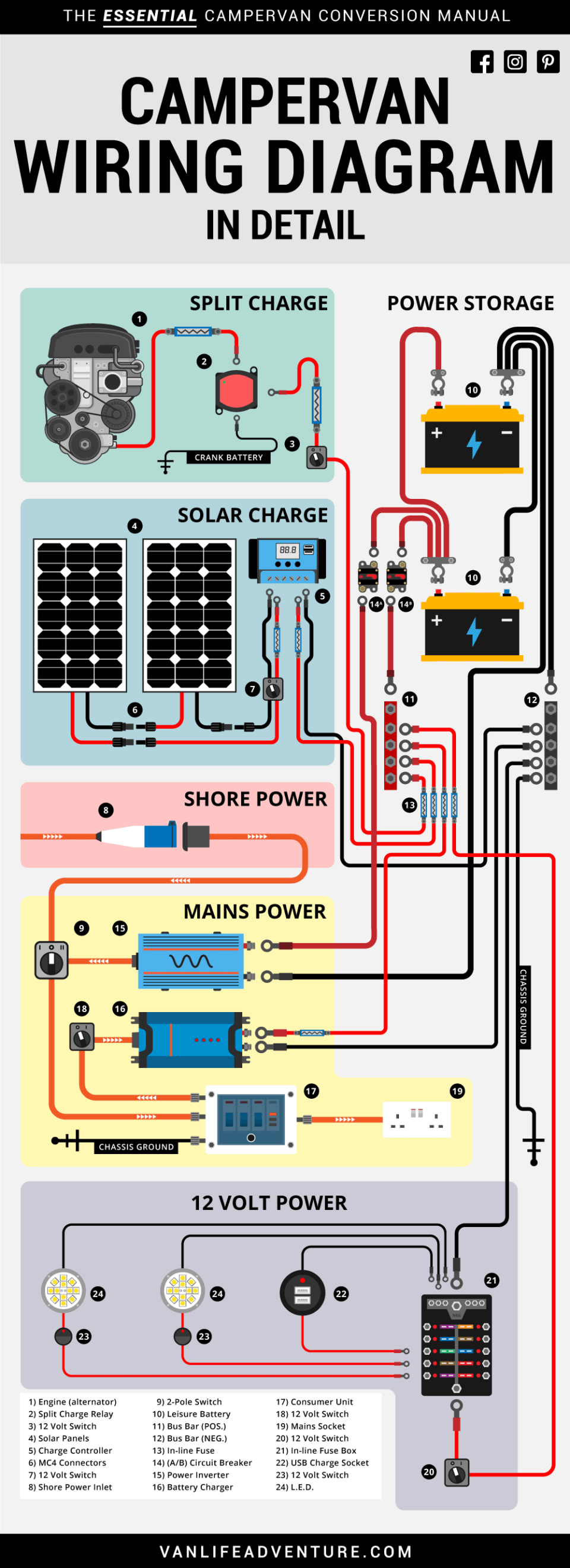
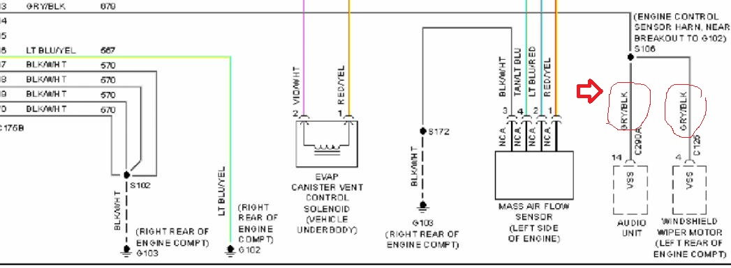
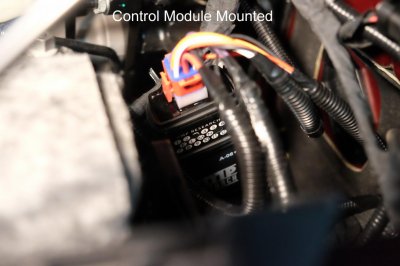
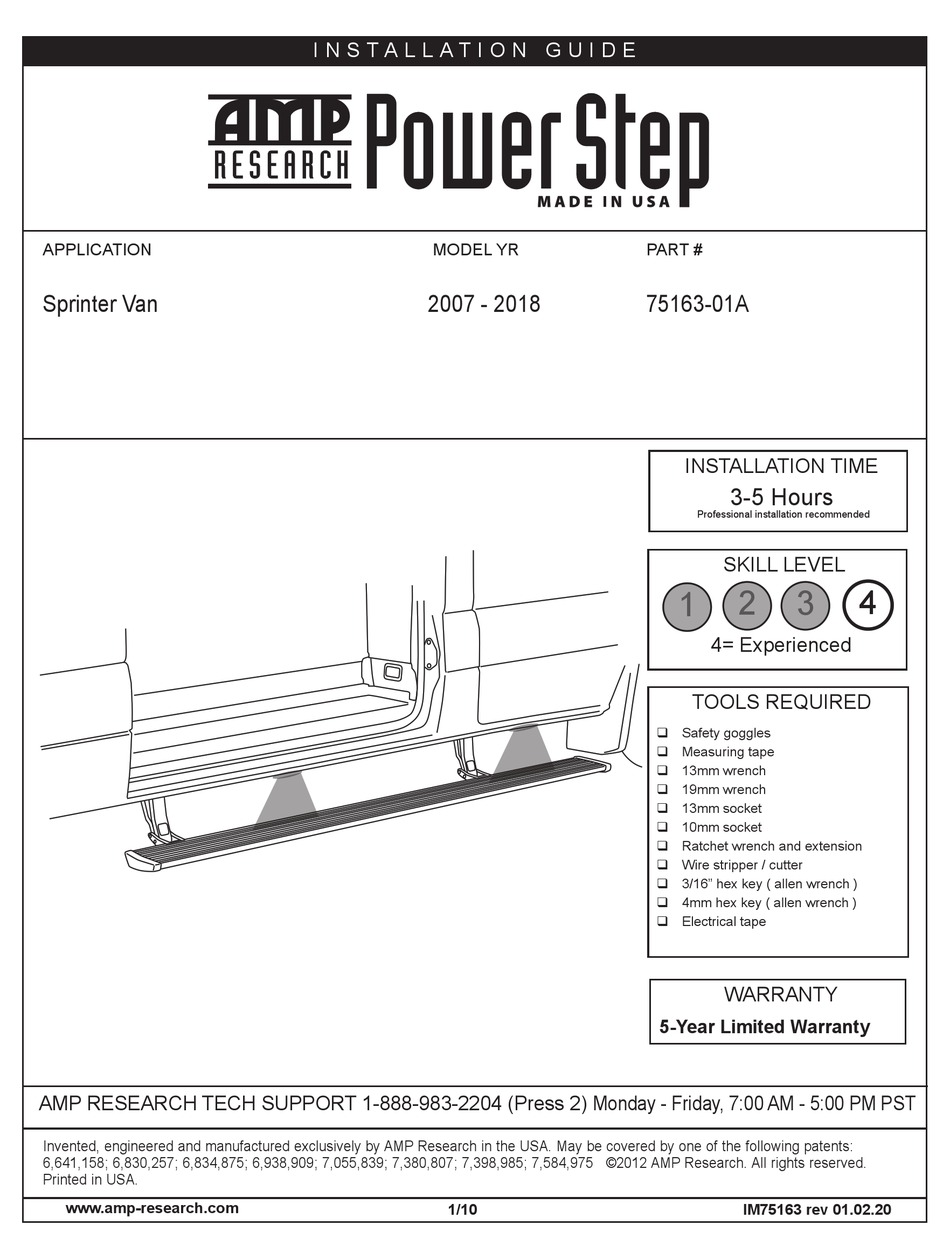
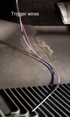
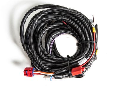
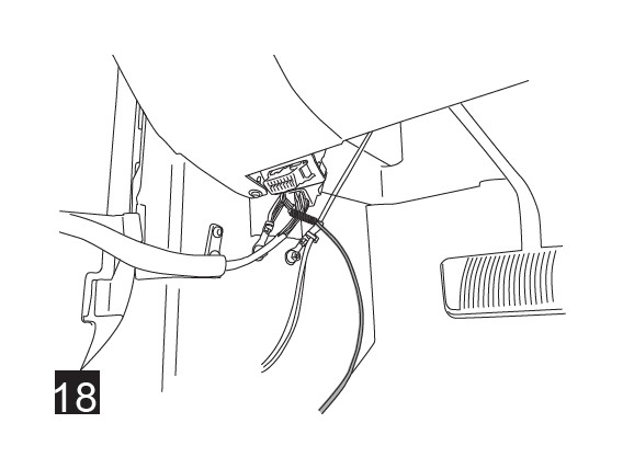
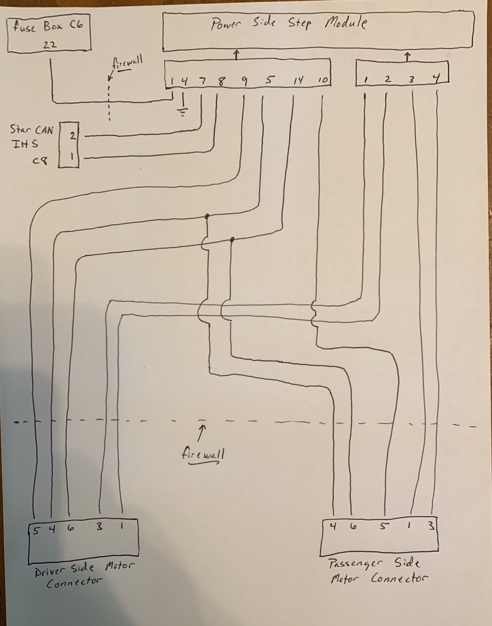
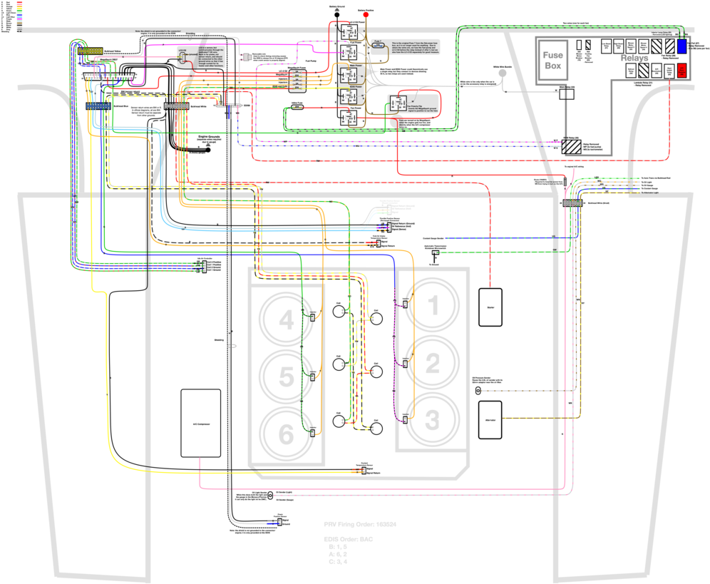
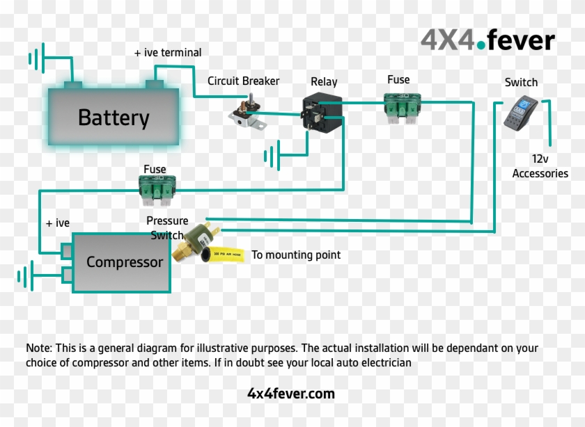
38 amp research power step wiring diagram
forums.autodesk.com › autodesk › attachmentsDiagrams, Device Designations, and Symbols for Industrial ... construction diagram: A diagram that shows the physical arrangement of parts, such as wiring, buses, resistor units, etc. Example: A diagram showing the arrangement of grids and terminals in a grid-type resistor. control sequence diagram: A portrayal of the contact positions or connections that are made for each successive step of the control ... › blog › tips-and-tricksSeymour Duncan Les Paul Wiring Diagram | Seymour Duncan Oct 04, 2013 · I used to set up my sound on a LP as a three channel amp… neck is clean, mid position is crunch, and treble pickup for lead… But the wiring is essential… Since then, my playing took a whole new turn. Tested and proved… My faded special LP with 50’s wiring sounded much closer to my 57 Goldtop reissue then my 2008 standard with modern ...
› Connect-Ceiling-Fan-WiresHow to Connect Ceiling Fan Wires (with Pictures ... - wikiHow Sep 14, 2021 · Turn off the power from the circuit or breaker box. Read the inside of your breaker or circuit box and locate the switch that controls the power to your fan. Once you find the right switch, flip it to the off position. It’s important that the power running to the wires in your ceiling is off or you could electrocute yourself.

Amp research power step wiring diagram
buildyourcnc.com › CNCelectronicsandWiringCNC Electronics and Wiring - Build Your CNC The wiring of the parallel breakout board from the output terminals to the driver digital pulse (step pulse) and direction lines are explained. The new parallel breakout board appears a bit different, but the process of wiring and testing is the same. Go to the new parallel breakout board to get more information and the wiring diagram. en.wikipedia.org › wiki › Power_supply_unit_(computer)Power supply unit (computer) - Wikipedia 12V only System monitoring (P10): This is a 171822-8 AMP or equivalent connector carrying a supply to the PSU fan and sense returns. ATX12V 4-pin power connector (also called the P4 power connector). A second connector that goes to the motherboard (in addition to the 24-pin ATX motherboard connector) to supply dedicated power for the processor. modernsurvivalblog.com › alternative-energy › aSolar Power System Diagram | 4 Basic Building Blocks Apr 26, 2021 · Solar power systems vary widely in their power producing capabilities and complexity. But I wanted to sketch a simple basic solar power system diagram that shows the building blocks. Regardless of a given system’s capacities and specifications, there’s a common thread among most of them: The basic building blocks of its major components. 1.
Amp research power step wiring diagram. joulesuites.us › mk3-relay-diagramMk3 relay diagram - joulesuites.us Clio Mk3 2006 - Burnt Relay (Change relay or fuse box This is the Diagrams#15631258: Renault Clio Wiring Diagram – Renault Clio Mk2 of a graphic I get coming from the 2004 Pontiac Volkswagen Golf mk3 fuse box diagram Auto Genius April 19th, 2019 - VW Golf mk3 – fuse box Volkswagen Golf mk3 – fuse box Volkswagen Golf mk3 – separate ... modernsurvivalblog.com › alternative-energy › aSolar Power System Diagram | 4 Basic Building Blocks Apr 26, 2021 · Solar power systems vary widely in their power producing capabilities and complexity. But I wanted to sketch a simple basic solar power system diagram that shows the building blocks. Regardless of a given system’s capacities and specifications, there’s a common thread among most of them: The basic building blocks of its major components. 1. en.wikipedia.org › wiki › Power_supply_unit_(computer)Power supply unit (computer) - Wikipedia 12V only System monitoring (P10): This is a 171822-8 AMP or equivalent connector carrying a supply to the PSU fan and sense returns. ATX12V 4-pin power connector (also called the P4 power connector). A second connector that goes to the motherboard (in addition to the 24-pin ATX motherboard connector) to supply dedicated power for the processor. buildyourcnc.com › CNCelectronicsandWiringCNC Electronics and Wiring - Build Your CNC The wiring of the parallel breakout board from the output terminals to the driver digital pulse (step pulse) and direction lines are explained. The new parallel breakout board appears a bit different, but the process of wiring and testing is the same. Go to the new parallel breakout board to get more information and the wiring diagram.










0 Response to "38 amp research power step wiring diagram"
Post a Comment