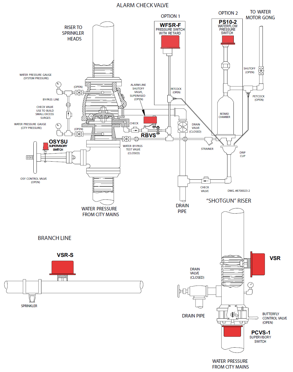
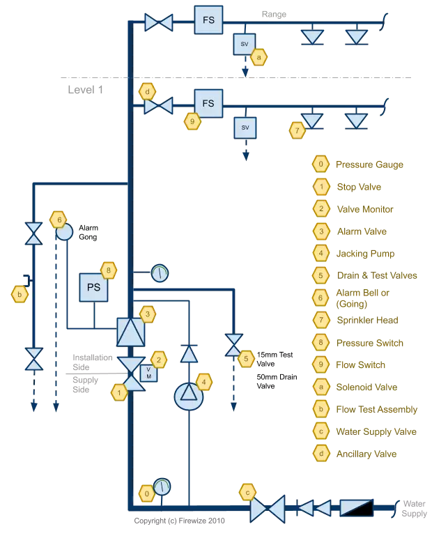
34 fire sprinkler riser diagram
Diagram must be legible and show the entire system. 2. Use professional standard symbols and legend. 3. Diagram is to be included on the CD (in dwg, dwf or pdf format), no paper submissions. 4. If the standpipe and sprinkler system is not a combination system, submit a separate riser diagram for each system. Locate the following: 06. Dry Pipe Sprinkler Riser Diagram.dwg. 06. Dry Pipe Sprinkler Riser Diagram.pdf: 7. 07. Pre-Action Sprinkler Riser Plan.dwg. 07. Pre-Action Sprinkler Riser Plan.pdf <page 1><Commercial><Residential><Symbols >
fire alarm riser notes: 1. use existing fire alarm control panel to perform the fire alarm functions as specified herein. existing panel may be reused if found to be capable of supporting devices as indicated. 2. all devices shall be building standard type or as specified. 3. see plans for location and quantities of fire alarm devices. all horn and
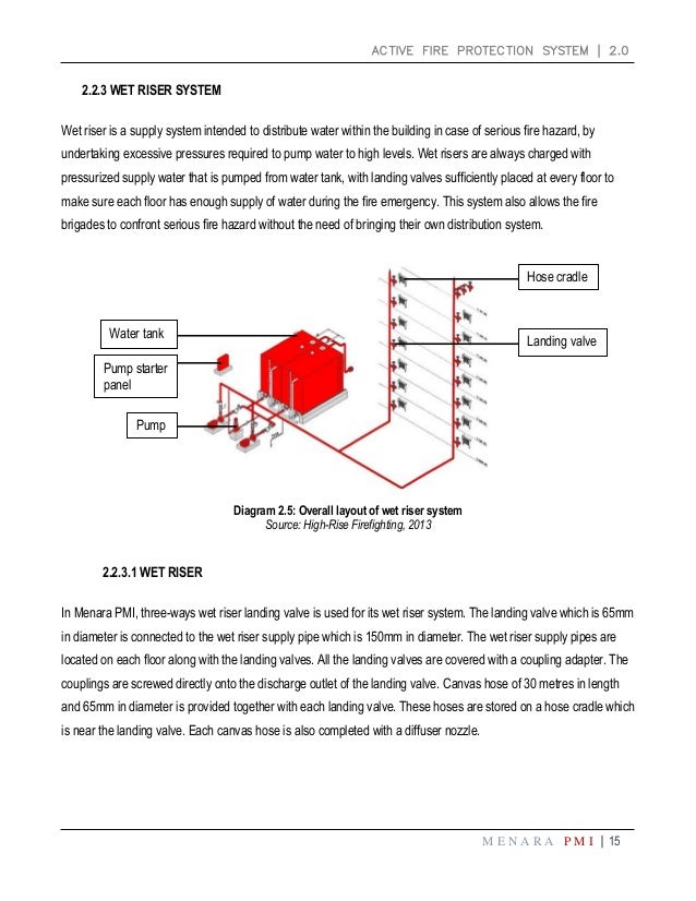
Fire sprinkler riser diagram
Each additional standpipe is required to flow 250 gpm to a maximum of 1,000 gpm for buildings protected with an automatic sprinkler system. For the sixth through 24th floors a total flow rate of 750 gpm was required due to the two standpipes, one in each exit stairway. As can be seen on the system riser diagram in Figure 1, the first through ... Best Practices Guide for Residential Fire Sprinklers Washington Fire Sprinkler Coalition │ 7 Washington State "Barriers Bill Background » Progress to date: » With the use of multi-purpose and flow-through sprinkler systems, increase meter sizes, hook-up fees and stand-by charges have been Riser Diagrams. A complete sprinkler or combination fire standpipe riser diagram is required for all sprinkler systems, showing the relevant portions of the existing building system and that portion of the system being modified. The diagram should include all system components including sizes and capacities, available water pressure, fire ...
Fire sprinkler riser diagram. (7) See Appendix "A" for riser diagram 7.1.5.1 FIRE RISER ASSEMBLY LOCATION AND ACCESS added (1) The riser shall be constructed within a garage or other secured location approved by Fire Code Official or within a wall cabinet or other acceptable enclosure with an access panel or door suitable for access to all riser components. Telephone-Data Equipment Closets and Riser Diagram : 08/14/08: D5030-2: 1: 2: Fire Alarm Riser Diagram : 09/25/06: D5030-3: 1: 0: Small Building Telecommunications Room Plan and Telecommunications Riser Diagram : 09/03/08: STANDARD DRAWINGS : ST-D5020-2: 1: 0: Haworth Furniture Wiring Diagram: 04/27/21: ST-D5020-2: 2: 0: Herman Miller Furniture ... Wet pipe sprinkler systems may be installed in any structure that is reliably maintained above 40 °F (4 °C), to automatically protect the structure, contents, and/or personnel from loss due to fire. Using water as its extinguishing agent, one wet system riser (or combined system riser) may cover as much as 52,000 Engineered Fire Systems, Inc. is a full service fire protection design and engineering company specializing in producing high quality fire sprinkler plans for any type of project. Sample Drawings. Below are actual examples of our fire sprinkler drawings. All of these drawings are saved in Adobe® PDF file format.
History of Fire Sprinklers ... Risers "rise" vertically through the floors to feed the Branch Lines Branch Lines then extend off the Risers and Mains horizontally to bring water to all the sprinkler heads. Town of Menasha Fire Department 8 Diagram. Town of Menasha Fire Department 9. Town of Menasha Fire 3. Riser diagram showing the essential features of the system, including the risers, cross-connections, valves, Fire Department Connections, tanks, pumps, sources of water supply, pipe sizes, capacities, floor heights, zone pressures, and other essential data and features of the system; and 4. A complete riser diagram • Details of the alarm equipment connections • A site plan showing connections to the water supply, PIV's, Fire Department connections and other pertinent components of the system • Any additions, deletions or corrections to the original plans must be approved by the Fire Systems Shop prior to the commencement ... Riser Nipples Sprinklers Figure 1. System Piping and Sprinklers. whether the valves are open or shut. A common example is an ... piping when the fire detection system and/or sprinklers (depending on the type of preaction system) are activated. The three types of preaction systems are listed below.
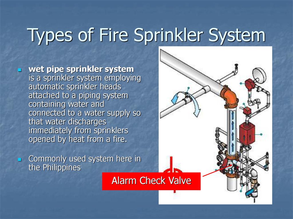
DRY PIPE SPRINkLER SYSTEM February 12, 2010 Page I. SYSTEM DESCRIPTION The Dry Pipe Sprinkler System is a fire-protection system that utilizes water as an extinguishing agent, while the system piping from the Dry Pipe Valve to the automatic fusible sprinklers is filled with pressurized air or nitrogen. Fire Sprinkler Parts & Inspection Terms. Picture this, you've just had your building's fire sprinkler system inspected and later receive a report from your fire sprinkler company. As you read through the report, you notice there are several deficiencies listed and repairs needed to be fixed in order to keep your building up to code. When the fire sprinkler head is activated, the alarm check valve opens. When the valve opens, the alarm port is exposed to the incom-ing water supply. The pressure switch detects the pressure change and sends an alarm. Wet Pipe Fire Sprinkler System with a Straight Pipe Riser Wet pipe fire sprinkler systems with straight pipe risers, located down- The sprinkler riser is the bridge between the underground and interior piping. This is the point where we supply the cross mains, feed mains and branch piping that make up the wet system piping network. It is at the sprinkler riser where we begin to make decisions on the components needed.
A fire protection system does more than protect the building. It is also a key component in the life safety strategy against fires. It both notifies the occupants of a fire and it suppresses the fire. For instance, if the building is a low-rise office or school building, fire sprinklers are proven to be greater value than smoke detectors.
3. Sprinkler system riser diagram. The riser diagram shall clearly identify number and types of existing and proposed electrical or automatic devices, sprinkler heads, valves, manifolds, pumps and pipe sizes. The riser diagram shall include: Siamese connection, curb box, valve assemblies, fire pumps, test tees, alarms
Riser diagrams. Riser diagrams are a schematic representation of the fire alarm system, identifying the central panel and remote devices. Thirty years ago, each room of the facility was identified along with the devices in that room. Today, the riser is much less detailed, as the example below, used on over 50 schools in different districts:
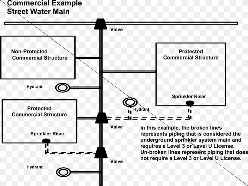
Standpipe Fire Sprinkler System Drawing Png 2497x1876px Watercolor Cartoon Flower Frame Heart Download Free
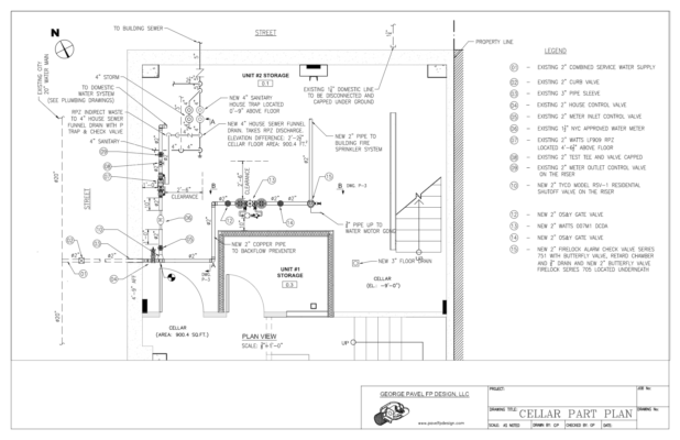
supply, to the sprinkler riser. The contract drawings must include a detailed sprinkler riser diagram. (2) Show location and size of service laterals, sprinkler risers, control valves, drain lines, sectional valves, and inspector's test valves and switches on the drawings. (3) Specify waterflow data including hydrant flow
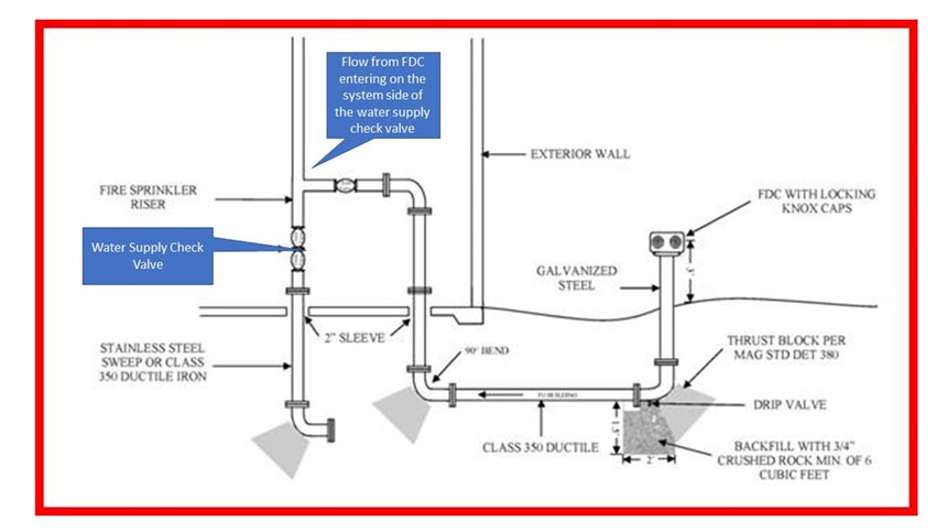
Purpose: Allows the fire department to supply supplementary pressure and flow to the system during a fire event. Where Required: on any sprinkler system that does not meet exceptions for being inaccessible, large-capacity deluge systems, or single-story buildings not over 2,000 sqft (185 sq.m.). (NFPA 13 2002 8.16.2.2, 2007-16 8.17.2.2, 2019 16 ...
the looped fire line to provide for isolation of the fire line. 5. fire sprinkler lines shall have a riser control piv for each individual riser. the piv's shall be located as close to the riser as practical. the riser control piv's may be eliminated when fd105 is used. fire sprinkler (fs) system riser (fd105) shall be shown on 6.
fire alarm riser diagram 1" conduit to main tele/data room basement floor first floor second floor fire alarm annunciator panel (faan) with remote microphone fire alarm sequence of operation ... fire sprinkler valve tamper switch smoke detector located in elevator lobby. 1. derive power for flashing warning light from visual alarm circuit in ...
Fire sprinkler risers are, in a sense, where the plumbing outside a building ends and a fire sprinkler system begins. Each riser taps into a permanent source of water, such as a pipe connected to the city water system, a water tank, or reservoir. Then, it conveys that water to the network of pipes running to fire sprinkler heads.
Automatic sprinkler system riser, fire pump and controllers shall be provided with ready access. Where located in a fire pump room or automatic sprinkler system riser room, the door shall be permitted to be locked provided that the key is available at all times. (IBC 2018 902.1.1) #3 - The fire riser is not required to be in any back of house ...
Prefabricated fire risers for commercial wet-pipe sprinkler systems generally feature: A short length of riser piping. A flow switch. The system-side pressure gauge and a three-way valve to turn it on and off. A drain valve or test and drain valve. A 6" prefabricated riser for commercial sprinkler systems.
Fire alarm system riser diagrams should include the following information: (1) General arrangement of the system in building cross-section (2) Number of risers (3) Type and number of circuits in each riser 72 A.
Riser Diagrams. A complete sprinkler or combination fire standpipe riser diagram is required for all sprinkler systems, showing the relevant portions of the existing building system and that portion of the system being modified. The diagram should include all system components including sizes and capacities, available water pressure, fire ...
Best Practices Guide for Residential Fire Sprinklers Washington Fire Sprinkler Coalition │ 7 Washington State "Barriers Bill Background » Progress to date: » With the use of multi-purpose and flow-through sprinkler systems, increase meter sizes, hook-up fees and stand-by charges have been
Each additional standpipe is required to flow 250 gpm to a maximum of 1,000 gpm for buildings protected with an automatic sprinkler system. For the sixth through 24th floors a total flow rate of 750 gpm was required due to the two standpipes, one in each exit stairway. As can be seen on the system riser diagram in Figure 1, the first through ...

Utilizing A Nitrogen Generator For Pre Action Systems In Critical Facilities Applications 2013 04 09 Mission Critical Magazine










0 Response to "34 fire sprinkler riser diagram"
Post a Comment