36 fe al phase diagram
(Fe) C, wt%C 1148ºC T(ºC) a Adapted from Figs. 9.24 and 9.32,Callister & Rethwisch 8e. (Fig. 9.24 adapted from Binary Alloy Phase Diagrams, 2nd ed., Vol. 1, T.B. Massalski (Ed.-in-Chief), ASM International, Materials Park, OH, 1990.) (Fe-C System) 6 C 0 Fe 3 C g g g g g g g g g g g Adapted from Fig. 9.33, Callister & Rethwisch 8e ... system, the phase diagram usually has the general appearance of that shown in Fig. 3. The diagram consists of two single-phase fields separated by a two-phase field. The boundary between the liquid field and the two-phase field in Fig. 3 is called the liquidus; that between the two-phase field and solid field is the solidus.
L. Zhang and R. Luck, Phase Diagram of the Al-Cu-Fe Quasicrystal Forming Alloy System: IV. Formation and Stability of the φ-Al 10 Cu 10 Fe 1 Phase, Z. Metallkde., Vol 94 (No. 3), 2003, p 341-344. Google Scholar 2003Zha5: L. Zhang and R. Luck, Phase Diagram of the Al-Cu-Fe Quasicrystal Forming Alloy System. V.
Fe al phase diagram
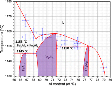
APPLICATIONS OF Fe-C PHASE DIAGRAM. KEY POINTS OF Fe-C Diagram Phases: •Liquid Fe-Tmin=1148C @ 4.3%C •1394 C<δ-Fe-<1538C •α-Ferrite (Ferrite)<912C; <0.02%C ... steels to which small additions of Al, Ti, and Nb were made. Quench Media •Quenchants are the medium in which a material The Al-rich part of the Fe-Al phase diagram between 50 and 80 at.% Al including the complex intermetallic phases Fe 5 Al 8 (ε), FeAl 2, Fe 2 Al 5, and Fe 4 Al 13 was re-investigated in detail. A series of 19 alloys was produced and heat-treated at temperatures in the range from 600 to 1100 °C for up to 5000 h. 1.1. Al-Fe-Si PHASE DIAGRAM The Al-Fe-Si system is the basic system for the structure analysis of commercial aluminum alloys of the 8111 type, and binary Al-Si alloys which, as a rule, contain an iron impurity (Table 1.1). The aluminum corner of the Al-Fe-Si phase diagram is considered in detail by Phillips (1959), who gives the isotherms of ...
Fe al phase diagram. Review Fe-C phase diagram • 2 important points-Eutectoid (B): γ⇒α+Fe 3C-Eutectic (A): L ⇒γ+Fe 3C Fe 3 C (cementite) 1600 1400 1200 1000 800 600 400 0 12 3 4 5 66.7 L γ (austenite) γ+L γ+Fe 3C α+Fe 3C α + γ L+Fe 3C δ (Fe) C o, wt% C 1148°C T(°C) α 727°C = Teutectoid A R S 4.30 Result: Pearlite = alternating layers of αand Fe ... ternary phase diagram of Ni-Cr-Fe. MSE 2090: Introduction to Materials Science Chapter 9, Phase Diagrams 11 Isomorphous system - complete solid solubility of the two components (both in the liquid and solid phases). Binary Isomorphous Systems (I) Three phase region can be identified on the phase diagram: Equilibrium diagram for the system NiO-Al z 0 (31) , 3 Equi'librium diagram for the system NiO-Alz0 3 (32) .. The Fe-O phase diagram (35,36).., Variation of wustite composition with 0z pressure and temperature. Fe-Al Sy~(8),. Fe-Al-Oisotherms proposed in reference (49) at 1000°C (a), l250°C (b), and 13500 C (c), NaA10Z-A1203 system as ... Phase diagrams Elastic properties First-principles calculations ABSTRACT The phase diagrams and elastic properties of the Fe-Cr-Al alloys in full-temperature and all-compositional ranges are calculated. By combining first-principles calculations and cluster variation method, binary and ternary phase diagrams are obtained.
Iron-Carbon Phase Diagram. The iron-carbon phase diagram is widely used to understand the different phases of steel and cast iron. Both steel and cast iron are a mix of iron and carbon. Also, both alloys contain a small amount of trace elements. The graph is quite complex but since we are limiting our exploration to Fe3C, we will only be ... Figure 1 - Phase diagram of the Zn-rich corner of the Zn -Fe-Al system at 860°F [460°C] as per reference 1 • When producing galvanize (h + L region of Figure 1), determining Al EFF consists of plotting the bath analysis results for Al TOT and total Fe on a phase diagram that is correct for the bath temperature at the time of sampling. A ... Fe-Si-Al flakes is about 1.7 as shown later. Thus, this means that the formation of the B2 phase was not suppressed during the gas-atomization process and the as-milled flakes also contain the B2 phase. This is due to the fact that the B2 phase is not stable at room temperature but stable at a temperature by X Li — All results combined with the obtained transition temperatures contribute to the updated Fe-Al phase diagram in the Al-rich part. The high- ...
The Fe-Al equilibrium phase diagram is shown in Figure 1, the IMP with allowable mechanical properties in case of weldings is marked. The system is characterized with an iron-based solid solution and six non-stoichiometric intermetallic compounds of Fe 3Al, FeAl (D 2), FeAl 2, Fe 2Al 3 (H), Fe 2Al 5 and FeAl 3. Table 1 indicates crystal ... by P Novák · 2013 · Cited by 77 — can be transformed to FeAl phase when fine powders were applied. Detailed mechanism is proposed in ... FeeAl equilibrium phase diagram [13]. P. Novák et al.10 pages by X Li · 2016 · Cited by 125 — The Al-rich part of the Fe-Al phase diagram between 50 and 80 at.% Al including the complex intermetallic phases Fe$_{5}$Al$_{8}$ (ε), ... 2.2. Al-Fe-^Mg PHASE DIAGRAM This phase diagram can be used to analyze the effect of iron on the phase compo sition of Al-Mg alloys with low concentrations of silicon and manganese. Examples of such alloys are given in Table 2.5. No ternary compounds have been found in the ternary Al-Fe-Mg system
The thermodynamic models used to describe the Fe-Al phase diagram are studied in detail. We calculate the phase diagram of Fe-Al within the Bragg-Williams approximation and the tetrahedron approximation of the cluster-variation method, including nearest- and next-nearest-neighbor chemical and magnetic interactions. In contrast to previous calculations performed within the Bragg-Williams ...
Though, it is noted that according to the phase diagram shown in Fig. 1 a two-phase field α-(Fe,Al)+Fe 3 Al exists which apparently extends to even lower Al contents than shown in Fig. 1. At 300 °C Ikeda et al. [24] found the A2/A2+D0 3 phase boundary at about 17 at.% and according to the slope of their data this phase boundary could extend ...

Potential Diagrams Chemical Potential Intensive And Extensive Parameters Types Of Phase Diagrams Unary Diagrams Binary Diagrams Ternary Diagrams Volatility Ppt Download
the Fe-Al-Zr phase diagram,[34] values of 1.8, 2.2, 0.7 at.% were given for the widths of the homogeneity ranges of these intermetallic compounds at 1000 C. Summarizing the above and having in mind that several lines in the Al-rich part of the Fe-Al phase diagram are still drawn as dotted lines today, it can be stated that this part of
Al-Fe Phase Diagram. Thermodynamic Assessment [1989Sei] M.Seiersten, unpublished work (1989). Available in SSOL2 and BIN database. [1993Kat] U.R.Kattner and B.P.Burton, Phase Diagrams of Binary Iron Alloys, (Ed.)H.Okamoto, ASM International, Materials Park, OH, 12-28 (1993). TDB File ...
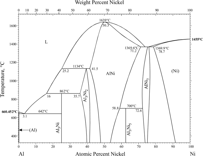
Supplemental Literature Review Of Binary Phase Diagrams Al Ni B Hf Ca Sc Cr Sc Fe Rh Hf Mn La Sb Ni Re Ni Sm Ni Zr Sb Tb And Ti Zr Springerlink
Phase Diagrams • Indicate phases as function of T, Co, and P. • For this course:-binary systems: just 2 components.-independent variables: T and Co (P = 1 atm is almost always used). • Phase Diagram for Cu-Ni system Adapted from Fig. 9.3(a), Callister 7e. (Fig. 9.3(a) is adapted from Phase Diagrams of Binary Nickel Alloys , P. Nash
The coherent phase diagram of the Fe-Al system possesses a tricritical point where a line of higher-order transitions ends at a miscibility gap at about 23 at.%. Al and 615°C. Rules of general ...
The Structural Phase Diagrams of Fe-Y (Y = Ga, Ge, Al) Alloys Mariya V. Matyunina, Mikhail A. Zagrebin, Vladimir V. Sokolovskiy, Vasiliy D. Buchelnikov Abstract. This work presents a theoretical study of structural and magnetic properties from first-principles calculations for binary Fe100-xYx type alloys (Y = Al, Ga, Ge) in concentration range 18.75 ≤ x […]
The Al-Si Phase Diagram The binary Al-Si phase diagram was initially studied by Fraenkel of Germany in 1908. It is a relatively simple binary diagram where there is very little solubility at room temperature for Si in Al and for Al in Si. Thus, the terminal solid solutions are nearly pure Al and Si under equilibrium conditions.
SGTE Alloy Phase Diagrams. Click on a system to display the phase diagram.
Si/Al Phase Diagram Most Si/Al alloys are cast near this eutectic point, they are cheap to manufacture; but cuboid Si flakes cause brittleness. Doping with 0.01% Na alters the compositional and temperature of the eutectic point (red lines): Alloy 2, which has the same relative amounts of Si and Al, now preciptates in a hypoeutectic fashion.

Scielo Brasil Experimental And Computer Thermodynamics Evaluations Of An Al Si Coating On A Quenchable Steel Experimental And Computer Thermodynamics Evaluations Of An Al Si Coating On A Quenchable Steel
The isothermal section of the Fe-Ni-Al phase diagram between 50 and 100 at.%Al at 850 °C was studied on 33 samples in sections at 60, 67, 71.5, 75 and 80 at.%Al, respectively. The results of XRD and EPMA analysis are summarized in the Table 1 and a graphical representation of phase equilibria is given in Fig. 1.Two ternary compounds were found at this temperature: τ1 (Fe 4−x Ni x Al 10 ...
Phase diagrams of the Al-Fe (a) and Al-Cr (b) boundary binary systems over the range . between 58 and 100 at.% Al. Al 75 Cr 16 Fe 9 alloys annealed at 1000°C contain one phase.
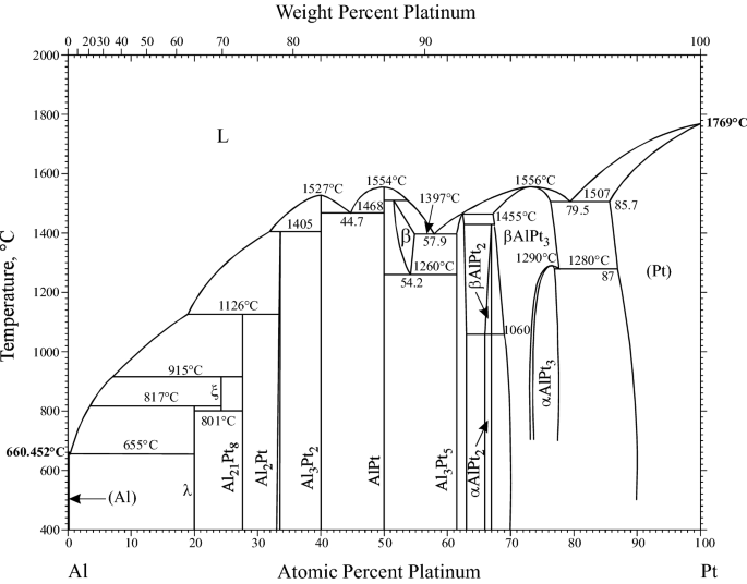
Supplemental Literature Review Of Binary Phase Diagrams Al Pt As U C Li C Mg Cd Nd Co Ta Fe Re Ga Y La Ni O V P Si And Re Zr Springerlink
192 / Phase Diagrams—Understanding the Basics. A hypothetical ternary phase space diagram made up of metals . A, B, and . C. is shown in Fig. 10.2. This diagram contains two binary eutectics on the two visible faces of the diagram, and a third binary eutectic between ele-ments . B. and . C. hidden on the back of the plot. Because it is ...
Download scientific diagram | Fe–Al binary phase diagram [12]. from publication: A study on the formation of iron aluminide (FeAl) from elemental powders ...

Fe Al Mn C Lightweight Structural Alloys A Review On The Microstructures And Mechanical Properties Iopscience
by J Wang · 2019 — Generally, the elements V, Mo, Nb can be added in Al–Fe alloy. The phase diagram can display the information of phase composition and phase ...

Interpretation Of Fe Rich Part Of Fe Al Phase Diagram From Magnetic Properties Of A2 B2 And Do3 Phases Sciencedirect
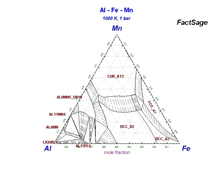
Al-Fe-P_1173K FSstel: Al-Fe-S_FeS-Al2S3 FTOxCN: Al-Fe-S2_900C FTOxCN: Al-Fe-Si_550C FSstel: Al-Fe-Si_1000K SGTE 2014: Al-Fe-Si_500K SGTE 2014. Al-Fe-Si_liquidprojection SGTE 2014: Al-Fe-Si_1000K SGTE 2017: Al-Fe-Si_1500K SGTE 2017: Al-Fe-Si_500K SGTE 2017: Al-Fe-Si_liq SGTE 2017: Al-Fe-Si_1000 SGTE 2020: Al-Fe-Si_1500 SGTE 2020: Al-Fe-Si_500 ...
by A Mulyawan · 2020 · Cited by 2 — Fe-rich part of binary Fe–Al phase diagram consists of three main phases: the disordered A2-phase (α-Fe, space group Im3m), the ordered B2-phase ...
1.1. Al-Fe-Si PHASE DIAGRAM The Al-Fe-Si system is the basic system for the structure analysis of commercial aluminum alloys of the 8111 type, and binary Al-Si alloys which, as a rule, contain an iron impurity (Table 1.1). The aluminum corner of the Al-Fe-Si phase diagram is considered in detail by Phillips (1959), who gives the isotherms of ...
The Al-rich part of the Fe-Al phase diagram between 50 and 80 at.% Al including the complex intermetallic phases Fe 5 Al 8 (ε), FeAl 2, Fe 2 Al 5, and Fe 4 Al 13 was re-investigated in detail. A series of 19 alloys was produced and heat-treated at temperatures in the range from 600 to 1100 °C for up to 5000 h.
APPLICATIONS OF Fe-C PHASE DIAGRAM. KEY POINTS OF Fe-C Diagram Phases: •Liquid Fe-Tmin=1148C @ 4.3%C •1394 C<δ-Fe-<1538C •α-Ferrite (Ferrite)<912C; <0.02%C ... steels to which small additions of Al, Ti, and Nb were made. Quench Media •Quenchants are the medium in which a material

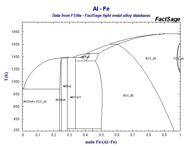




0 Response to "36 fe al phase diagram"
Post a Comment