37 ignition coil ballast resistor wiring diagram
17 Oct 2017 — Use of this device reduces the risk of coil failure. It is installed in the circuit between the primary voltage source for the ignition coil and ... Ignition Coil Ballast Resistor Wiring Diagram. Find this Pin and more on Wiring Diagram Free by Wiring Forums. Led Fluorescent. Led Tubes. Rx7. Fancy Cars. Ignition Coil. Diagram. Wire.
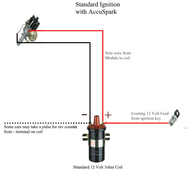
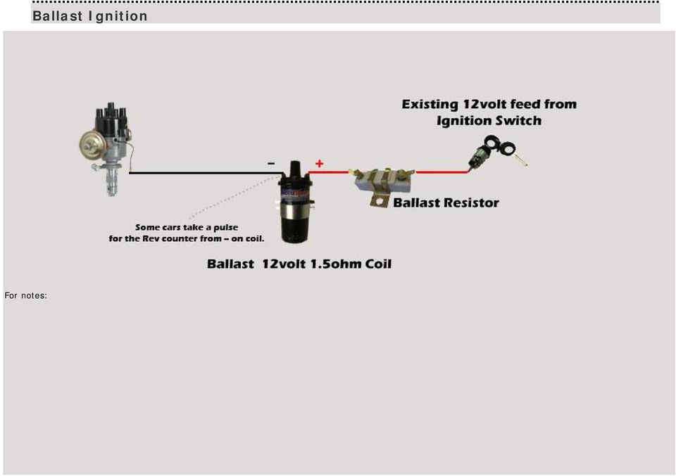
The ballast resistor and coil + is connected as per the diagram. The ballast resistor is used to reduce the voltage at the coil during normal running. A 12V ...

Ignition coil ballast resistor wiring diagram
The transistor ignition system features a specially designed distributor, ignition pulse amplifier, and a special coil. Two resistance wires are also used in the circuit; one as a ballast between the coil negative terminal and ground, while the other resistance wire provides a voltage drop for the engine run circuit Description : Ignition Coil Ballast Resistor Wiring Diagram with Ignition Coil Ballast Resistor Wiring Diagram, image size 609 X 360 px, and to view image details please click the image. Here is a picture gallery about ignition coil ballast resistor wiring diagram complete with the description of the image, please find the image you need. A resistor wire or ballast resistor may or may not be included in the original equipment. The typical automotive ignition system prior to 1974 consisted of a coil and ballast resistor with breaker points to interrupt the current flow when a spark was needed. Diagram Wiring Diagram Ballast Resistor Ignition Coil Full Version Hd Quality …
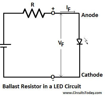
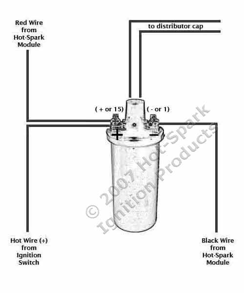
Ignition coil ballast resistor wiring diagram. Our Ballast Resistor is designed to be used in conjunction with our available External Resisted Ignitions Coils. External Resisted Ignition Coils have an internal resistance of 1.5 Ohms and when combined with the Ballast Resistor you get a total resistance of 3.0 Ohms which is necessary for 12 Volt ignitions systems. A ballast resistor is a resistor inserted into a circuit to compensate for different changes. The coil does not go direct to earth. Mopar Ballast Resistor Wiring Diagram Basic Electronics Wiring Diagram I am planning to replace the distributor with a mallory unilite pointless distributor the instructions emphasize the necessity of either a ballast resistor […] Ignition Coil Ballast Resistor Wiring Diagram. Print the cabling diagram off plus use highlighters to be able to trace the circuit. When you use your finger or even follow the circuit together with your eyes, it is easy to mistrace the circuit. 1 trick that We use is to print the same wiring picture off twice. COIL WIRE. TO IGNITION SWITCH. RED WIRE. BLACK WIRE. RESISTANCE WIRE. BALLAST RESISTOR. The Ignitor can also be installed in applications retaining the ...4 pages
About Press Copyright Contact us Creators Advertise Developers Terms Privacy Policy & Safety How YouTube works Test new features Press Copyright Contact us Creators ... The typical automotive ignition system prior to 1974 consisted of a coil and ballast resistor, with breaker points to interrupt the current flow when a spark was needed. The job of the ballast resistor was to inhibit current to a level that would not overheat the coil. This simple system is easy for even the novice mechanic to wire. 19 Mar 2019 · 9 posts · 7 authorsBallast resistor goes in series with the white wire from ignition switch (fuse box A1 terminal) to ignition coil. You can mount the ballast ... Step 4: Install Ballast Resistor. Set the ballast resistor up to the firewall and screw the clamps in place. Step 5: Connect Wires to Positive. Strip the end of the positive wire from the ignition, and connect it to the positive end of the resistor. From the other terminal on the resistor a wire goes to the positive on the coil.
If there is power there, the ballast resistor is likely bad. Reconnect the wires and measure the voltage at the positive side of the coil. If you see 8-13 volts ... A resistor wire or ballast resistor may or may not be included in the original equipment. The typical automotive ignition system prior to 1974 consisted of a coil and ballast resistor with breaker points to interrupt the current flow when a spark was needed. Diagram Wiring Diagram Ballast Resistor Ignition Coil Full Version Hd Quality … Description : Ignition Coil Ballast Resistor Wiring Diagram with Ignition Coil Ballast Resistor Wiring Diagram, image size 609 X 360 px, and to view image details please click the image. Here is a picture gallery about ignition coil ballast resistor wiring diagram complete with the description of the image, please find the image you need. The transistor ignition system features a specially designed distributor, ignition pulse amplifier, and a special coil. Two resistance wires are also used in the circuit; one as a ballast between the coil negative terminal and ground, while the other resistance wire provides a voltage drop for the engine run circuit
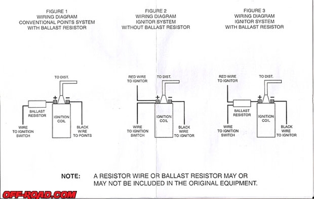
Ballast Resistor Ignition Wiring Electronic Ignition Units Ballast Resistors The H A M B Shefalitayal
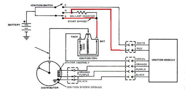
Electronic Ignition And Ballast Resistors Question Mg Engine Swaps Forum Mg Experience Forums The Mg Experience
How To Wire Mid 1970s Through Mid 1980s Ignition Systems Retrofitting Electronic Ignition On Vehicles That Originally Had Points Allpar Forums

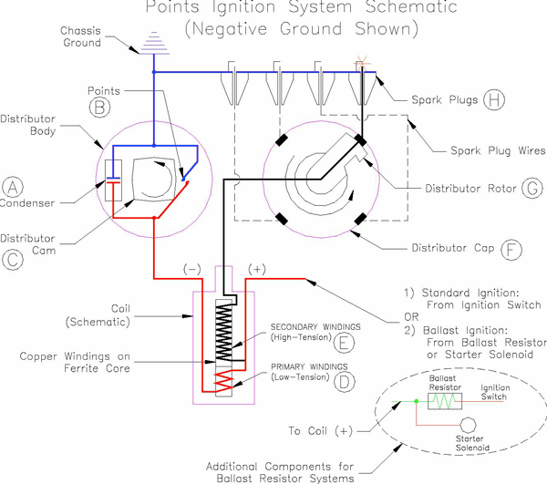

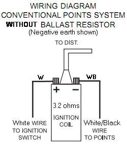






0 Response to "37 ignition coil ballast resistor wiring diagram"
Post a Comment