38 ttt diagram for eutectoid steel
Time Temperature Transformation curve and its significance is discussed in tamil. It will help you understand the concept behind the heat treatment processes... TTT curve of eutectoid steel superimposed on iron carbon phase diagram. The curve is prepared by heating steel samples to the austenitizing temperature of 1,550°F (845°C). These samples are then quenched to a set of temperatures below 1,300°F (700°C).
In lesson nine. Determination of TTT diagram for eutectoid steel. Davenport and Bain were the first to develop the TTT diagram of eutectoid steel. They determined pearlite and .TTT Diagram • The TTT digrams for hyper-eutectoid steels will differ from that of eutectoid steels • The TTT diagrams for hyper-eutectoid steels will have an ...

Ttt diagram for eutectoid steel
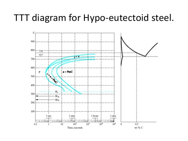
TTT diagram of hypoeutectoid and hypereutectoid steels AISI 9261 steel is not austempered as the holding-time Fig. 3.9. Schematic diagram for austempering superimposed on TTT diagram, may be greater than 24 hours. Carbon steel parts of only small size (5 mm for AISI 1080) are austempered due to very high cooling rates needed to avoid pearlitic transformation. Compare TTT diagrams for hypoeutectoid, eutectoid and the hypereutectoid steels in Fig. 3.6. The incubation period is maximum (critical cooling rate is slowest) in eutectoid steel. M s temperatures are uniformly decreasing in the whole range of carbon. Bainitic part is uniformly shifted to the right. (b) Effect of Alloying Elements:
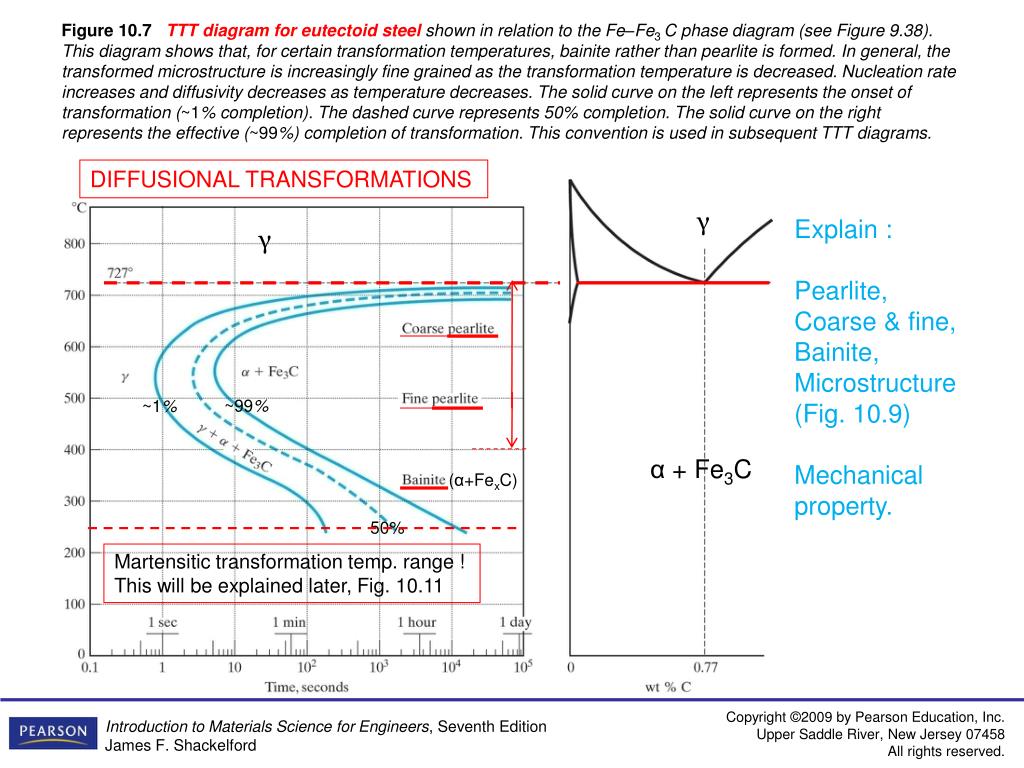
Ttt diagram for eutectoid steel. TTT Diagram For Eutectoid Steel ( Isothermal Transformation Diagram ) Time-Temperature-Transformation (TTT) diagram or S-curve refers to only one steel of a particular composition at a time, which applies to all carbon steels. This diagram is also called as C-curve isothermal (decomposition of austenite) diagram and Bain's curve. Iron-Iron Carbide Phase Diagram - Callister. Austenite is a polymorph of iron, in a face centred cubic (FCC) structure. Carbon is relatively soluble in this phase (up to 2% C at 1100°C). It is therefore found in mild carbon steel above the eutectoid temperature of 727°C. As it cools, the austenite transforms into the much less carbon soluble ... In the process of heat treatment of steel, the identification of various kinds of transformed structure and the start-end points of phase transformation can be estimated by using a time temperature transformation (TTT) diagram and/or a continuous cooling transformation (CCT) diagram as shown, respectively, in Figure 3(a) and 3(b). Effect of Alloying elements in Steel and Phase diagram. Type -1: Open Gamma Field. Type - 2: Expanded Gamma Field. Type - 3 Closed gamma field. Type - 4 Contracted gamma field. Classification of Effect of Alloying elements in Steel. Effect of Alloying element in steel on Eutectoid Point. Distribution of Alloying Elements in steel.
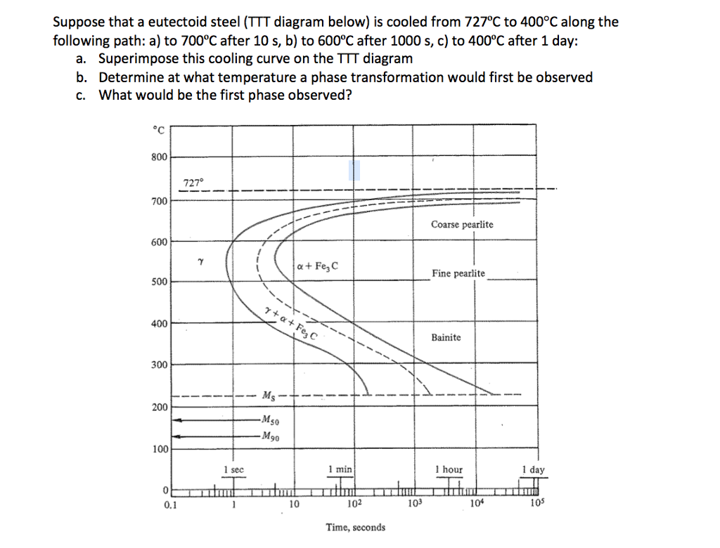
We'll examine the lead-tin phase diagram and look at its practical applications as an example of making something slowly. Then we'll evaluate the TTT diagram for eutectoid steel, and compare diffusional to diffusionless transformations with the TTT diagram, monitoring how we make things rapidly. Lesson ten is a brief history of semiconductors. Scribd is the world's largest social reading and publishing site. A slow cooling path that leads to coarse pearlite formation is superimposed on the TTT diagram for eutectoid steel. AISI-SAE - % C be different than a TTT diagram. 15 Slow Cooling Time in region indicates amount of microconstituent! TTT Diagram On the other hand, TTT diagram is a more practical diagram. It shows what structures can be expected after various rates of cooling. It graphically describes the cooling rate required for the transformation of austenite to pearlite, bainite or martensite. TTT diagram also gives the temperature at TTT diagrams for eutectoid and 4340 steel alloys . Author: mveiseh Created Date: 9/26/2002 3:22:58 AM
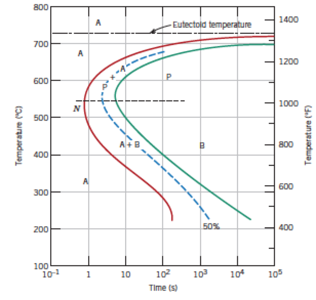
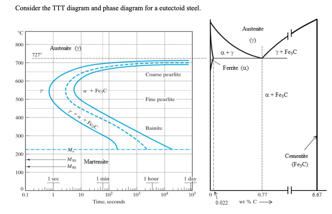
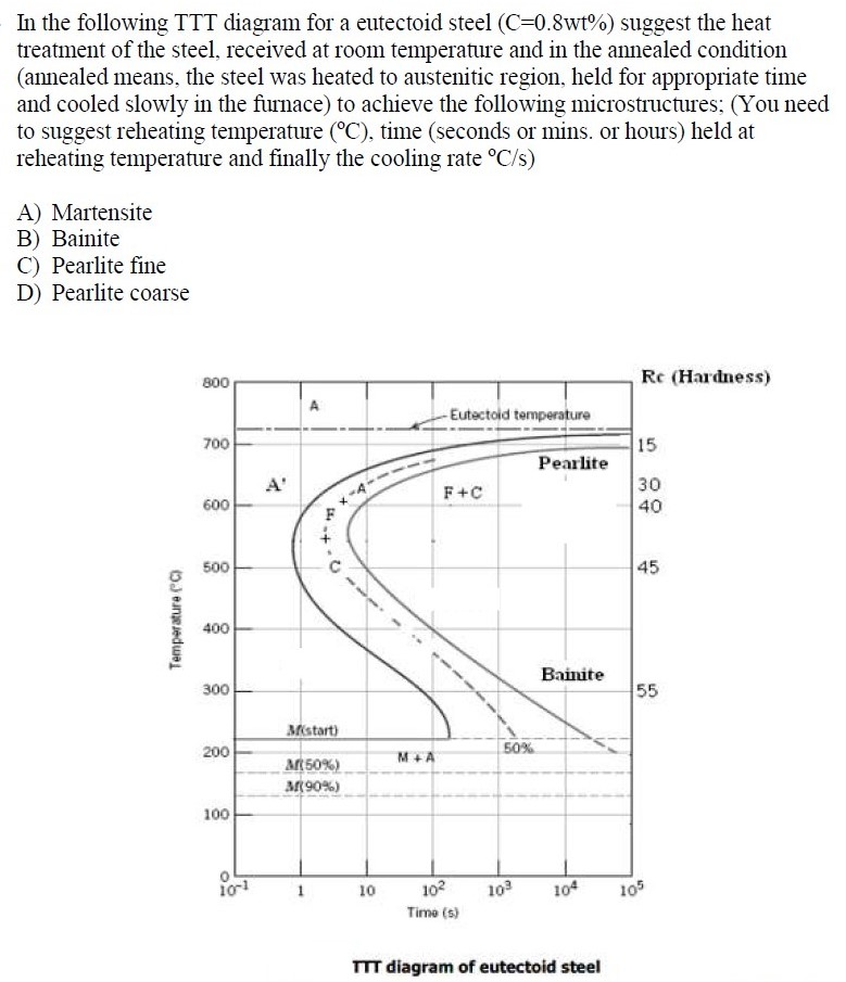
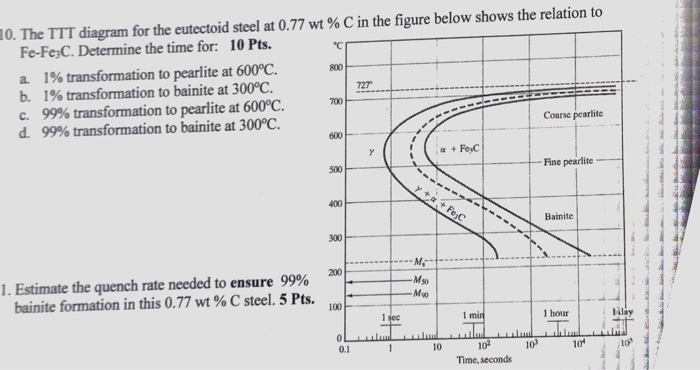
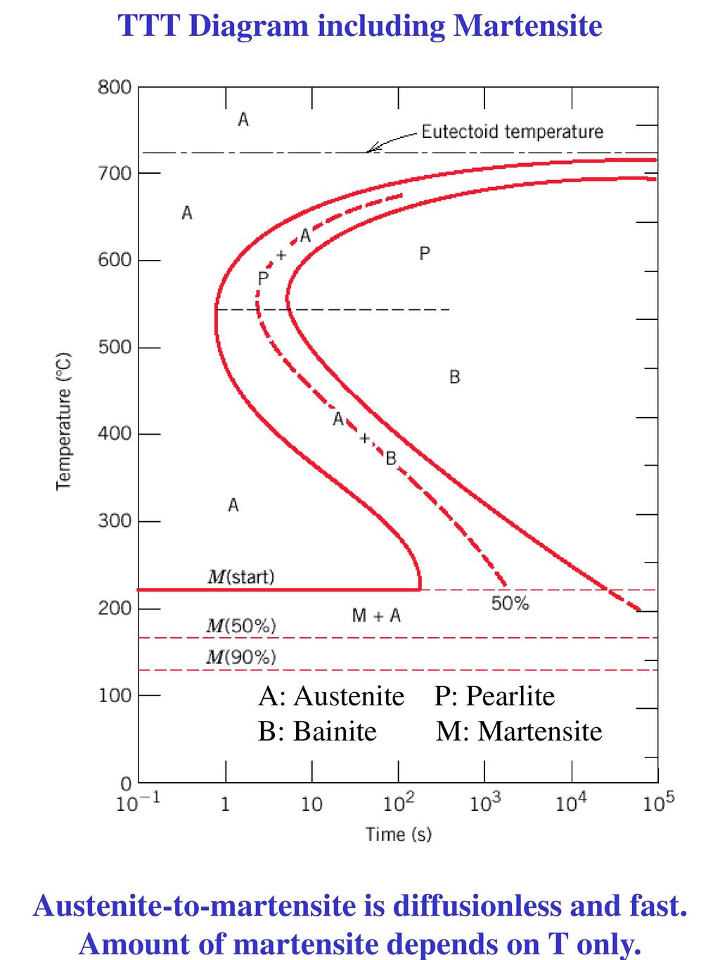
TTT diagram is a plot of temperature versus the logarithm of time for a steel alloy of The complete isothermal transformation diagram for an iron-carbon alloy.C metastable equilibrium diagram and TTT diagrams for plain carbon hypoeutectoid, eutectoid and hypereutectoid steels M S (a) Fe-Fe 3 C metastable phase diagram (b) TTT diagram for ... The diagram is known as an I-T (isothermal-transformation) diagram. Other names for the same curves are TTT (transformation, temperature, time) curves or S curves. The I-T diagram for 1080 eutectoid steel is shown in the figure given below. Above the Ae 1 austenite is stable. The area to the left of the beginning of transformation consists of ... Such a TTT diagram for eutectoid steel is shown in Figure 1. The microstructures that result from various heat treatments are dependent on the cooling rate from the austenite range; they are predicted using the TTT diagram with superimposed cooling curves for the selected material. TTT diagram of eutectoid steel . 4 If you draw a horizontal line at any temperature, the line may (or may not) cut the curves at different time scales. For example, a line drawn at 800 C, cuts only the first curve, which is the ferrite start. It means: if the steel, heated initially to 850 C
Fe3C at Eutectoid Transformation ... be different than a TTT diagram. 15 Slow Cooling Time in region indicates amount of microconstituent! 16 Medium Cooling Cooling Rate, R, is Change in Temp / Time °C/s. 17 Fast Cooling This steel is very hardenable… 100% Martensite in ~ 1 minute of cooling! 18
Presented above is the TTT-diagram for eutectoid steel.For each composition, there will be a slight variation in diagram curves. TTT diagram of steel indicates the time-temperature and transformation curve. This means transformation is dependent upon time, temperature, and cooling mechanism.
the iron-carbon alloy system. A sample of the eutectoid composition is cooled from a single-phase region (γ) to a temperature (T) below the eutectoid temperature (T E). The following diagram shows a part of the iron-carbon phase diagram. Concentrations C 1, C 2, C 3, C 4 are various equilibrium ( stable as well as metastable ) concentrations ...
Explanation: TTT Diagram: The rate of phase transformation also depends upon the temperature.; Temperature-time-transformation diagram (TTT), also known as isothermal transformation curves, are useful in planning heat treatments. The complete isothermal transformation diagram for an iron-carbon alloy of eutectoid composition A (austenite), B (Bainite), M (Martensite), P (Pearlite) is below:
It can be seen that heat treatment and principally the cooling rate is critical to obtaining the required microstructure in carbon steel. The simplest approach explaining the effect of cooling rate on restructure is to consider a time-temperature-transformation (TTT) curve, but this is a subject for another blog. References. 1. W.
Pearlite is eutectoid of steel. It has been found that the proportion of pearlite increases from nothing in the case of pure carbonless iron upto 100%, or saturation, for steel containing 0.90% of carbon thus a 0.3 percent carbon steel will consist of about 33 percent pearlite and rest ferrite.
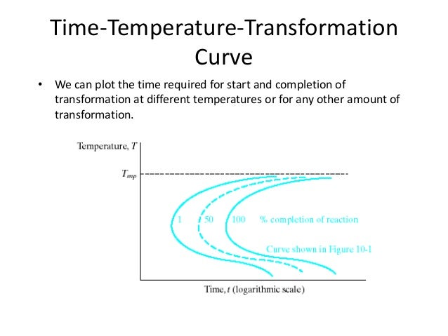
2. T-T-T diagram is plotted for different length of times and temperature These curves gives us the information of transformation for different phases With the help of T-T-T diagram we can control the phase transformation by changing the conditions. 3. The left side of C-shape curve is Austenitic region The right side of C- shape curve contain ...
Steel with a 0.78 wt% C is said to be a eutectoid steel. Steel ... (TTT) diagram shown in Figure 6-2. As a sample is cooled, the temperature will decrease as shown in curve #1. At point A, pearlite (a mixture of ferrite and cementite) will start to form from ... Isothermal transformation diagrams for SAE 1045 steel are shown in Figure 6-4. Heat ...
TTT Diagram • The TTT digrams for hyper-eutectoid steels will differ from that of eutectoid steels • The TTT diagrams for hyper-eutectoid steels will have an additional curve to show the precipitation of cementite from martensite before transformation of remaining austenite to pearlite 53. TTT diagram for a hypereutectoid Steel (1.13 wt% C) 54.
Determination of TTT diagram for eutectoid steel Davenport and Bain were the first to develop the TTT diagram of eutectoid steel. They determined pearlite and bainite portions whereas Cohen later modified and included M S and M F temperatures for martensite. There are number of methods used to determine TTT diagrams. These are salt bath (Figs. 1-
Using the TTT diagram for a eutectoid, plain-carbon steel given below, describe the microstructures at the end-points for each heat treatments (a) through (f). 800 600 100% TTT 400 -200LM. Question: 3. Using the TTT diagram for a eutectoid, plain-carbon steel given below, describe the microstructures at the end-points for each heat treatments ...
TTT diagrams for (a) eutectoid, (b) hypoeutectoid, and (c) hypereutectoid steels. (b) and (c) show (dashed lines) the C-curves for the formation of primary α and Fe 3 C, respectively. Note that as the carbon content increases, both M s and M F decrease.
RT - Room Tempearture. Use I for 0% Transformed as an answer! --Given Values-- Time Temperature Transformation Diagram: -1050 Steel Heat Treatment: - Quench to 1000F hold for 5 seconds then quench to RT then; Question: Instructions: For the following problems utilize the listed TTT Diagram from your Equation Booklet. The treatment begins with ...
In such steels, pro-eutectoid ferrite is first formed before the pearlite reaction begins and this is shown in the TTT curve by a third decomposition line. From Figure 12.4(b) it can be seen that the amount of pro-eutectoid ferrite decreases as the isothermal transformation temperature is lowered. The morphology of the precipitated ferrite ...
Consider the TTT diagram and phase diagram for a eutectoid steel. TTT If a specimen of this steel is solutionized (aka, annealed to equilibrium) at 750°C for 1 day and then rapidly quenched to 300oC where it is held for 5 days.

The Ttt Diagram For Eutectoid Steel Making Things Fast And Slow A Brief History Of Semiconductors Coursera
hypoeutectoid steel and by cementite in hypereutectoid steel. Schematic T TT diagrams for eutectoid, hypoeutectoid and hyper eutectoid steel are shown in Fig.", Figs. 7(a)-(b) and all of them together along with schematic Fe-Fe3C metastable equilibrmm are shown in Fig. 8.

Small Specimens Of Eutectoid Composition Have Been Held At 760 Oc Long Enough To Achieve A Complete And Homogenous Austenitic Structure Using The Ttt Diagram For An Iron Carbon Alloy Of Eutectoid Com
Compare TTT diagrams for hypoeutectoid, eutectoid and the hypereutectoid steels in Fig. 3.6. The incubation period is maximum (critical cooling rate is slowest) in eutectoid steel. M s temperatures are uniformly decreasing in the whole range of carbon. Bainitic part is uniformly shifted to the right. (b) Effect of Alloying Elements:
AISI 9261 steel is not austempered as the holding-time Fig. 3.9. Schematic diagram for austempering superimposed on TTT diagram, may be greater than 24 hours. Carbon steel parts of only small size (5 mm for AISI 1080) are austempered due to very high cooling rates needed to avoid pearlitic transformation.
TTT diagram of hypoeutectoid and hypereutectoid steels









0 Response to "38 ttt diagram for eutectoid steel"
Post a Comment