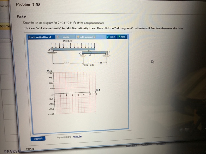
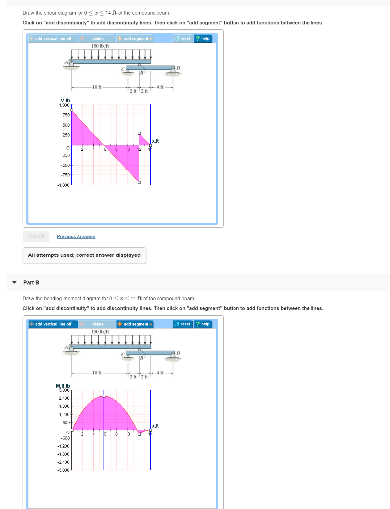
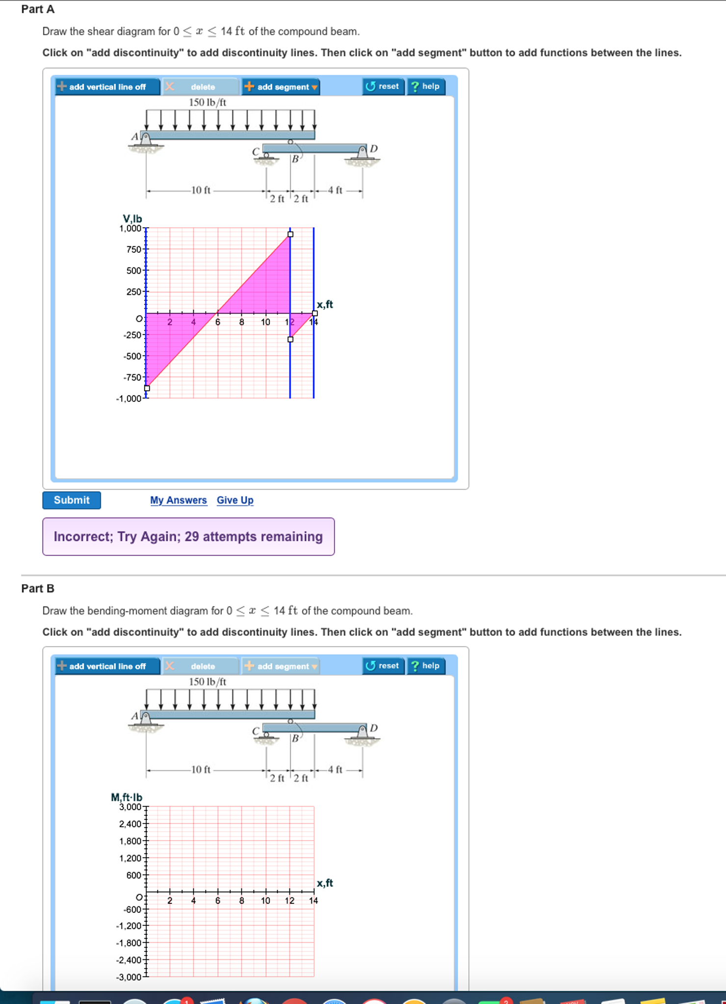
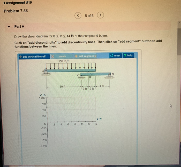
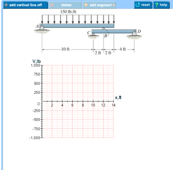
33 draw the shear diagram for 0 ≤ x ≤ 14 ft of the compound beam.
C = {(x, y)| x = cos(t), y = sin(t), 0 ≤ t ≤ 2π} Note that in FreeFem++ the domain Ω is assumed to described by its boundary that is on the left side of its boundary oriented by the parameter. As illustrated in Fig. 2.2, we can see the isovalue of u by using plot (see line 13 below).
Nov 10, 2021 · Draw the shear diagram for 0 ≤ x ≤ 14 ft of the compound beam. Draw the shear and moment diagrams for the beam. (figure 1) Draw the product(s) formed by heating the following compound in basic ethanol. Draw the product obtained by heating each pair of ketones in a basic solution. Draw the product formed when oleic acid is hydrogenated.
If the elevator can accelerate at a1, decelerate at a2, and reach a maximum speed v, determine the shortest time to make the lift, starting from rest and ending at rest. Given: h 48 ft= a1 0. 6 ft s 2 = a2 0. 3 ft s 2 = v 8 ft s = Solution: Assume that the elevator never reaches its maximum speed.
Draw the shear diagram for 0 ≤ x ≤ 14 ft of the compound beam.
Take A Sneak Peak At The Movies Coming Out This Week (8/12) New Movie Releases This Weekend: December 10-12; A Very HollyGOOD Christmas Playlist
Transcribed image text: Draw the shear diagram for 0 lessthanorequalto x lessthanorequalto 14 ft of the compound beam. Click on "add discontinuity" to add discontinuity lines. Then click on "add segment" button to add functions between the lines.
O Scribd é o maior site social de leitura e publicação do mundo.
Draw the shear diagram for 0 ≤ x ≤ 14 ft of the compound beam..
May 26, 2018 · Draw the shear and moment diagrams for the beam and determine the shear and moment in the beam as functions of x where 4 ft x 10 ft. 60 k 8 ft. 100010 200 20 0 490 lb b y y m a a m 50x 490 v m v 490 v lb 980 x 510 m lbft 2401 200 fig a fig b 5 15.
Vibrations are oscillations of a mechanical or structural system about an equilibrium position. Vibrations are initiated when an inertia element is displaced from its equilibrium position due to an energy imparted to the system through an external
CV Valve size in inches 0.3 1 4 3 14 35 55 108 174 400 725 1 1 3 4 6 8 2 1 1 2 2 8 OR 12. a) Explain cavitations and flashing in detail. Draw pressure variation diagram for above condition. Also explain its effects on control valve. b) List any 4 selection criteria for control valve. c) List any 4 application of control valve.
EXAMPLE 2.1 GRA PHIC A L C ON S T R U C T I ON OF A F OU R -B A R M E C H A N I S M For the given link lengths of a four-bar mechanism and the position of link 2, construct the permissible geometries of the mechanism r1 =10.0 cm; r2 = 4.0 cm; r3 = 8.0 cm; r4 = 5.0 cm; θ2 = 30° SOLUTION We first draw links 1 and 2 in their specified ...
14 13 12 11 10 9 8 7 6 5 4 3 2 1 0 0 Force on Top Bars Bottom Bar Force 180 Time in Degrees 360 GE Proprietary Information Stator Winding Mechanical Design April 26, 2000 7 GE Power Generation Technology 16 15 14 13 12 Force in pounds per inch of length 11 10 9 8 7 6 5 4 3 2 1 0 0 Time in Degrees 180 360 Bottom Bar Force Force on Top Bars Current
Draw the shear and bending moment diagrams for the beam. A y 1225 2100 0 a y 875 lb. Solution 14 ft of the compound beam. Draw the shear diagram for 0 x 14 ft of the compound beam. 1225162 c y182 0 c y 91875 lb c f y 0. The shaft is supported by a smooth thrust bearing at a and a smooth journal bearing at b.
1 inch (in) 2.540 cm or 1 cm 0.3937 in 1 foot (ft) 30.48 cm 1 mile (mi) 1.609 km or 1 km 0.6214 mi 1 cm 0.3937 in 1 m 39.37 in 3.2808 ft 1.0936 yd 1 km 0.6214 mile 1 nautical mile 1.15 mile Area (metric) 1 m2 106 mm2 1 mm2 10 6 m2 1 m2 104 cm2 1 cm2 10 4 m2 1 hectare (ha) 104 m2
4.6 Shear stress and shear strain 4.7 Poisson's ratio (v) 4.8 Hydrostatic stress 4.9 Relationship between the material constants E, G, K and v 4.10 Three-dimensional stress 4.11 Composite materials 4.12 Thermal strain 4.13 Compound bars 4.14 Failure by fatigue 4.15 Failure due to creep 5 Geometrical properties of symmetrical sections 5.1 ...
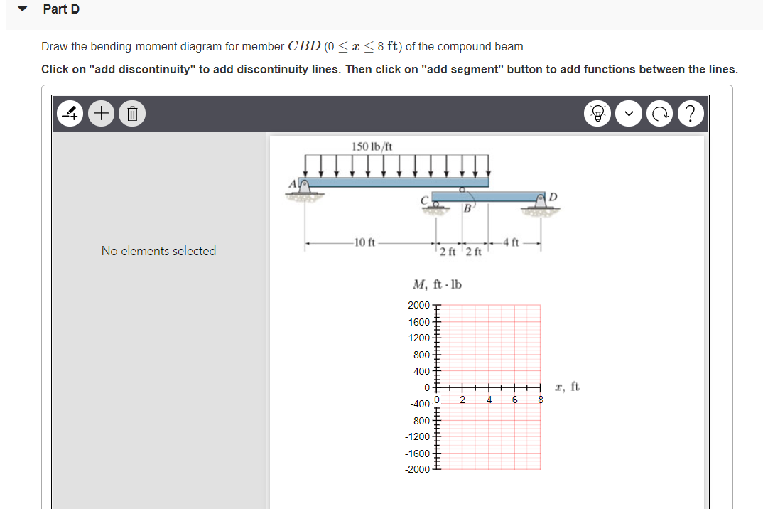
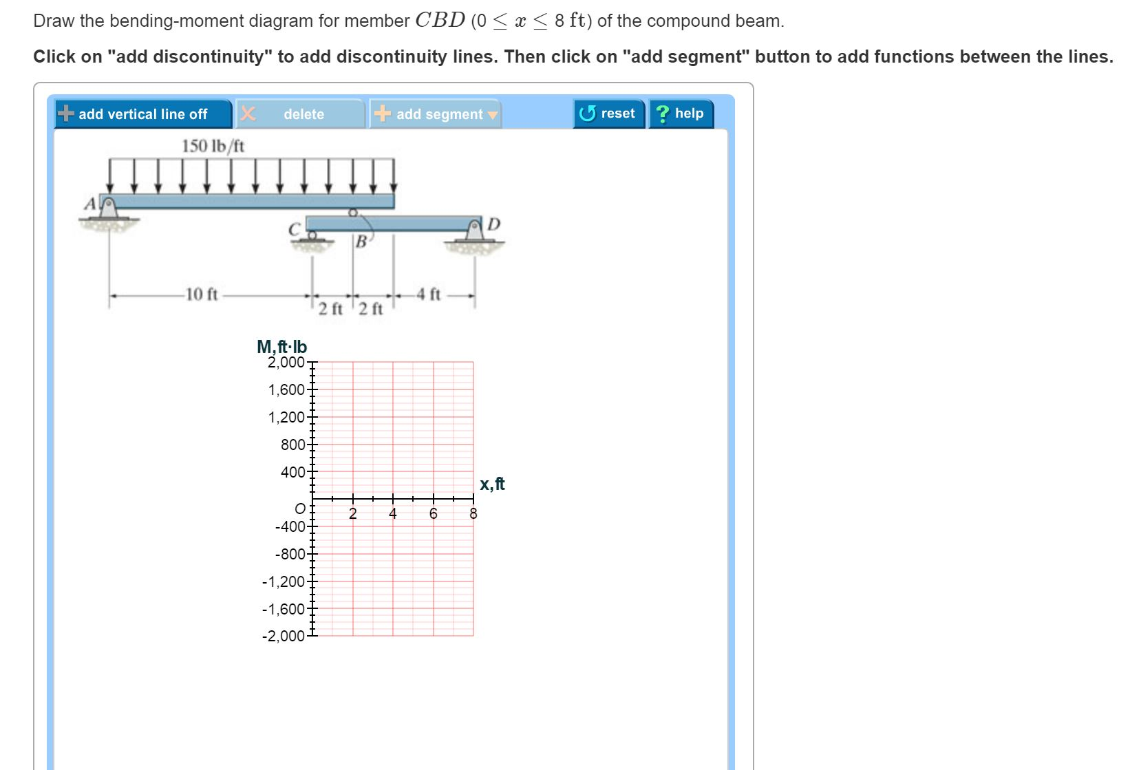
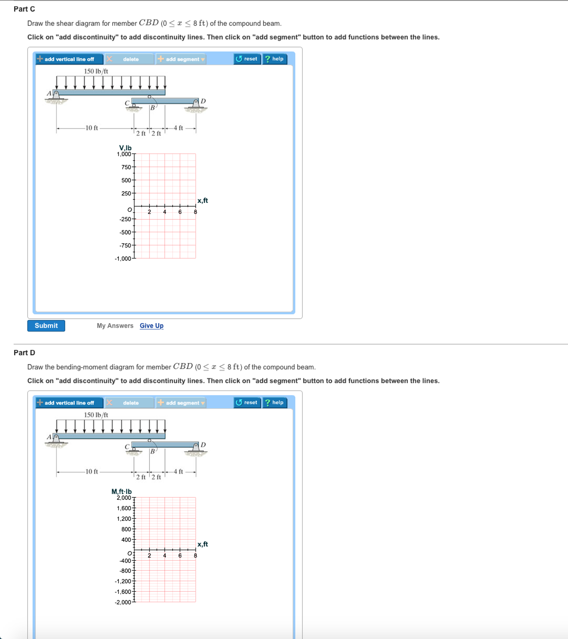
Draw the shear diagram for 0. Draw the shear and bending moment diagrams for the beam. Part c draw the shear diagram for member cbd 0 x 8 ft of the compound beam. The support at a is a thrust bearing and at b it is a journal bearing. This problem has been solved. Part d draw the bending moment diagram for member cbd 0 x 8 ft of the compound beam.
Abstract. In this chapter, the fundamentals of design of conveying and construction machinery will be presented. Machines that fulfill transportation tasks in limited operating areas such as mines, ports, work and storage yards, as well as construction sites are most common and can be found in any type of industry.
Academia.edu is a platform for academics to share research papers.
Heat, thermal analysis and society, Nucleus 2004, 380pp, 20 [email protected] Printed and bound by VČT, Pardubice. Includes bibliographical references and index data.
Further permissions questions can be e-mailed to [email protected] Library of Congress Control Number: 2008924835 ISBN-13: 978--495-10836-8 ISBN-10: -495-10836-7 Brooks/Cole 10 Davis Drive Belmont, CA 94002-3098 USA Cengage Learning is a leading provider of customized learning solutions with office locations around the globe, including ...
Questions Q.1 - Q.25 carry 1mark each. Questions Q.26 - Q.55 carry 2marks each. Questions Q.56 - Q.60 carry 1mark each, and questions Q.61 - Q.65 carry 2marks each. For all 1 mark questions, ⅓ mark will be deducted for each wrong answer. For all 2 marks questions, ⅔ mark will be deducted for each wrong answer. However, in the case ...
The effect of different values of K on the shape of the yield surface in the -plane is shown in Figure 2.20. To ensure convexity of the yield surface, the range 0.778 ≤ K ≤ 1.0 should not be violated. Associated flow is used in the extended Cam clay model (i.e., the plastic potential is the same as the yield surface).
Nov 17, 2016 · M0 x v k shear and moment diagrams draw the shear and moment diagrams for the following beam l w0 x m. The support at a is a thrust bearing and at b it is a journal bearing. Ch06 07 Pure Bending Amp Transverse Shear Draw the shear and moment diagrams for the double overhanging beam. Draw the shear diagram for 0 x 14 ft of the compound beam ...
Part A Draw the shear diagram for 0 < 14 ft of the compound beam. Click on "add discontinuity" to add discontinuity lines. Then click on "add segment" button to add functions between the lines ?help add segment add vertical line off delete reset 150 lb/ft AA D B 10 ft 4 ft 2 ft 2 ft 1,000. 750- 500 250 |x,ft O 4. 2 6 8 10 12 14 -250 -500 -750 ...
N. Korea's parliamentary session. This photo, released by North Korea's official Korean Central News Agency on Sept. 30, 2021, shows Kim Song-nam, director of the International Department of the ruling Workers' Party's Central Committee, who was elected as a member of the State Affairs Commission, the country's highest decision-making body, during the second day of a session of the Supreme ...
Referring to the FBD of the left segment of the beam sectioned at x = 3 ft shown in Fig. a, the internal moment at x = 3 ft is a+ΣMO = 0; M + 1 2 (600)(3)(1) = 0 M = -900 lb # ft 7-85. Draw the shear and moment diagrams for the beam. 6 ft3 ft 3 ft 600 lb/ft B A Ans: x = 3+ V = 1800 lb M = -900 lb # ft x = 6 V = 0 M = 1800 lb # ft
0.125 mm  ½ °° °° 50 u 0.5 Ž1 ž 2 ° S u 0.010 u 200 u 106 ° 4 ¯° ¿° kx 50 u 0.125 ? Compressive stress = 0.07945MPa A § S u 0.0102 ¡ ¨ ¸ 4 ...
Aug 08, 2019 · Draw the shear and moment diagrams for the beam. 1225162 c y182 0 c y 91875 lb c f y 0. Draw the shear diagram for 0. 14 ft of the compound beam. Home study engineering mechanical engineering mechanical engineering questions and answers draw the shear diagram for 0. A m 75x2 1050x 3200 ans 200 150x 4 x 4 2 m 0.
2.5.3 Mohr's Circle for Simple Shear An element acted upon by only shear stresses is shown in Figure 2.14(a). In this case, px = 0, py = 0 and only the shear stress q exists. Since the stresses px and py are zero, the radius of Mohr's circle is q.
P = b Ab = 32[ 78 (0 375)(8) ] P = 84 kips Bearing strength on the beam: The thickness of beam W18 × 86 is 0.480 inch while that of the clip angle is 2 × 0.375 = 0.75 inch (clip angles are on ...
Jan 10, 2016 · 1225162 c y182 0 c y 91875 lb c f y 0. Draw the shear diagram for 0 x 14 ft of the compound beam. Draw the shear and moment diagrams for the beam shown in the figure. B m 0 v 52100 150x6 lb c f y 0. M kn 65 140 50 25 v m kn kn. 875 150x v 0 0 x12 ft c f y 0.
Multiply 2.2 and 0.225. Give the answer correct to significant figures. Solution : 2.2 × 0.225 = 0.495 Since the least number of significant figure in the given data is 2, the result should also have only two significant figures. ∴ 2.2 × 0.225 = 0.50 1.5 Convert 76 cm of mercury pressure into N m-2 using the method of dimensions.
the shaft axis are subjected to shear stresses only. Normal stresses, shearing stresses or a combination of both may be found for other orientations. ( ) max 0 max 0 45 max 0 max 0 2 2 2 cos45 2 o τ τ σ τ τ = = = = = A A A F F A A • Consider an element at 45 o to the shaft axis, • Element a is in pure shear. • Note that all stresses ...
Draw the shear diagram for 0 ≤ x ≤ 14 ft of the compound beam. - A body is said to be in equilibrium, if the algebraic sum of all the forces acting on the
essais gratuits, aide aux devoirs, cartes mémoire, articles de recherche, rapports de livres, articles à terme, histoire, science, politique
If the speed of sound in water is 1450 m s-1, then calculate the distance of the enemy ship. 1.27 State the number of significant figures in the following: (i) 600900 (ii) 5212.0 (iii) 6.320 (iv) 0.0631 (v) 2.64 × 1024 1.28 Find the value of π2 correct to significant figures, if π = 3.14. 1.29 5.74 g of a substance occupies a volume of 1.2 ...









0 Response to "33 draw the shear diagram for 0 ≤ x ≤ 14 ft of the compound beam."
Post a Comment