33 the following diagram shows resistors in and is of the arrangement of circuit elements in homes.
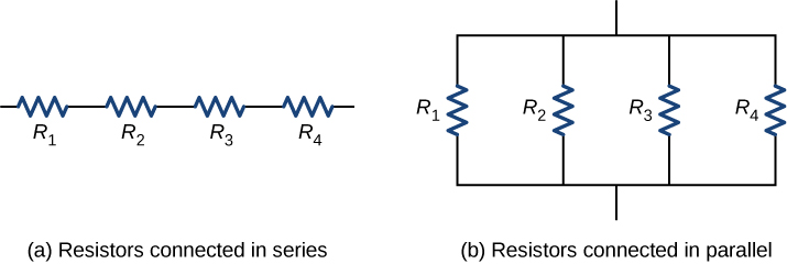
Transcribed image text: R1 R3 R2 R4 W The circuit in the diagram contains one battery and four resistors, labeled 1 through 4. ? Which of the following is true about the way that the circuit elements are arranged Resistors 1 and 2 are in parallel while resistors 3 and 4 are in series Resistors 1 and 4 are in parallel while resistors 2 and 3 are in series Resistors 1 and 4 are in series, while ...
11.2 Ohm's Law (ESBQ6) Interactive Exercise 11.2. Try the interactive questions. Three quantities which are fundamental to electric circuits are current, voltage (potential difference) and resistance. To recap: Electrical current, I, is defined as the rate of flow of charge through a circuit. Potential difference or voltage, V, is the amount of ...
The following diagram shows resistors in ___ and is ____ of the arrangement of circuit elements in homes. 1. A. series B. parallel 2.

The following diagram shows resistors in and is of the arrangement of circuit elements in homes.
The given circuit diagram shows the experiment arrangement of different circuit components for determination of equivalent resistance of two resistors connected in series. The components X, Y and Z shown in the circuit respectively represent. [1] (a) Rheostat, Resistor Ammeter (b) Voltmeter, Ammeter, Rheostat (c) Ammeter Voltmeter, Rheostat
Different types of electric circuits show different behaviors (parallel and simple ... to use the electricity – like a light bulb or a resistor or a buzzer.
Feb 27, 2018 — The following diagram shows resistors in ___ and is ____ of the arrangement of circuit elements in homes. 1. A. series. B. parallel2 answers · Top answer: i wanna say that .....Electrical things in parallel are typical of circuit elements ...
The following diagram shows resistors in and is of the arrangement of circuit elements in homes..
The diagram at the right shows two identical resistors - R1 and R2 - placed in a circuit with a 12-Volt battery. Use this diagram to answer the next several ...
The diagram shows a simple type of car rear window heater. The six heating elements are exactly the same. Each heating element has a resistance of 5 Ω. The current passing through each element is 0.4 A. (i) Calculate the total resistance of the six heating elements. Show clearly how you work out your answer.
If this arrangement of three resistors was to be replaced by a single resistor, its resistance should be: ... V 1, V 2 and V 3 are the p.ds. across the 1Ω, 2Ω and 3Ω resistors in the following diagram, and the current is 5 A. Which one of the columns (a) to ... Draw a circuit diagram to show the connections. (b) Calculate the current drawn ...
The feedback network of an op-amp circuit may contain, besides the resistors considered so far, other passive elements. Capacitors and inductors as well as solid state devices such as diodes, BJTs and MOSFETs may be part of the feedback network. In the general case the resistors that make up the feedback path may be replaced by
The diagram shows the circuit diagram for a two-slice electric toaster that is operated at a mains voltage of 230 V. € 5 The toaster has four identical heating elements and has two settings: normal and low. On the normal setting both sides of the bread are toasted. On the low setting, only one side of the bread is toasted.
The logic diagram does not show the electrical characteristics of a circuit such as current, voltage or power etc. it only represents the logical function of the circuit or device where the signal is considered in binary format i.e. 1 or 0. Logic diagram are commonly used in digital logic designing.
The diagram below shows a circuit with one battery and 10 resistors; 5 on the left and 5 on the right. Determine… the current through; the voltage drop across; the power dissipated by each resistor; Given the circuit below… Calculate the equivalent resistance of the circuit. Calculate the current through the battery.
Line Diagram. It is a simplified notation of an electrical system, also called as One-Line Diagram or Single Line Diagram. It is similar to the block diagram except that various electrical elements such as transformers, switches, lights, fans, circuit breakers, and motors are represented by standard schematic symbols.. It consists of symbols to represent the components and lines to represent ...
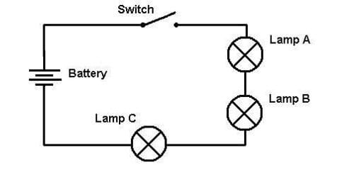
1. In the circuit below, the switch is initially open and bulbs A and B are of equal brightness. When to the brightness of the two bulbs? A. The brightness of the bulbs is not affected.
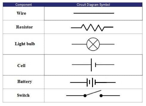
This module is divided into three (3) lessons, namely: Lesson 1: Resistors in series and parallel Lesson 2: Kirchhoff's rules Lesson 3: R-C circuits After you have finished the content of this module, you will be able to: 1. draw circuit diagrams with power sources (cell or battery), switches, lamps, resistors (fixed and variable) fuses ...
encounter for resistors R1, R2 and R3? A. drop, drop, drop B. gain, gain, gain C. drop, gain, gain D. gain, drop, drop E. drop, drop, gain In the following circuit, consider the loop abc. The direction of the current through each resistor is indicated by black arrows. "going with current is drop, against current is gain"
The figure shows a circuit that illustrates the concept of loops, which are colored red and labeled loop 1 and loop 2. Loop 1 is the loop around the entire circuit, whereas loop 2 is the smaller loop on the right. To apply the loop rule you would add the voltage changes of all circuit elements around the chosen loop. The figure contains
11.1 series circuits | series and parallel circuits | siyavula
The following diagram shows resistors in ___ and is ____ of the arrangement of circuit elements in homes.1. A. series. B. parallel
Resistors in series and parallel | physics ii
Figure 27-27 shows a circuit of four resistors that are connected to a larger circuit.The graph below the circuit shows the electric potential V(x) as a function of position x along the lower branch of the circuit, through resistor 4; the potential VA is 12.0 V. The graph above the circuit shows the electric potential V(x) versus
Physicsandmathstutor.com
The circuit on the left in Figure 3 shows two resistors in series. When circuit elements are connected across common points such that there is more than one conducting path through the circuit, they are connected in parallel. The circuit on the right in Figure 3 shows two resistors in parallel.

Diagram of the arrangement of elements on the circuit board ...
The diagram below shows the circuit for a small convector heater. Heater elements can be switched in and out of the circuit using switches X and Y. Each element has a resistance R and the power supply has an emf V. (a) The table shows the possible combinations of open and closed switches. When a switch is closed, charge can flow through it. 17

Igcse 0625_s16_qp_12core flashcards | quizlet
For example, the circuit in is known as a multi-loop circuit, which consists of junctions. A junction, also known as a node, is a connection of three or more wires. In this circuit, the previous methods cannot be used, because not all the resistors are in clear series or parallel configurations that can be reduced. Give it a try.

Diagram of the arrangement of elements on the circuit board ...
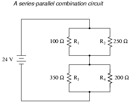
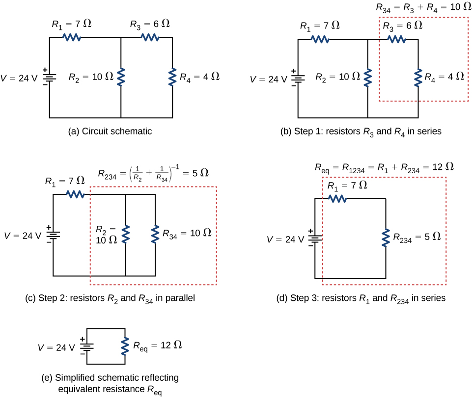
Determine whether resistors are in series, parallel, or a combination of both series and parallel. Examine the circuit diagram to make this assessment. Resistors are in series if the same current must pass sequentially through them. Use the appropriate list of major features for series or parallel connections to solve for the unknowns.
![Parallel and series circuit Physics [NWIS] (0) boys Quiz ...](https://quizizz.com/media/resource/gs/quizizz-media/quizzes/3e7a5d0f-8752-4e2a-9159-eb3f4e6b815c)
Parallel and series circuit physics [nwis] (0) boys quiz ...
The following diagram shows resistors in _____ and is_____ of the arrangement of circuit elements in homes. series, not typical. In the following diagram, the voltage is 1.5 volts and the resistance is 6.0 ohms. Use Ohm's law to determine the current in the circuit.
Physicsandmathstutor.com
Questions 14-15 refer to the following diagram that shows part of a closed electrical circuit. 14. The electrical resistance of the part of the circuit shown between point X and point Y is (A) 4/3 (B ) 2 (C) 4 (D) 6 15. When there is a steady current in the circuit, the amount of charge passing a point per unit of time is
Resistors in series and parallel – university physics volume 2
An RL circuit (sometimes called an RL filter or RL network) is an electrical circuit made up of the passive circuit elements of a resistor (R) and an inductor (L) linked together and driven by a voltage or current source. An RL circuit, like an RC or RLC circuit, will consume energy due to the inclusion of a resistor in the ideal version of the ...
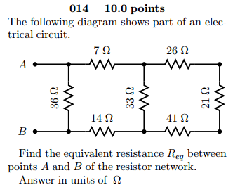
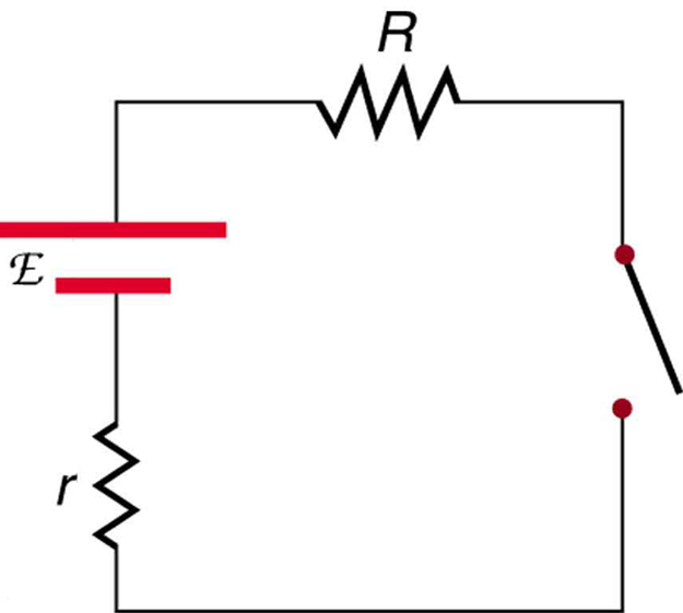
Solved the following diagram shows part of an electrical ...
In the circuit diagram shown, R1, R2, and R3 are three resistors of different values. R3 is greater than R2, and R2 is greater than R1. ε is the electromotive force of the battery whose internal resistance is negligible. Which of the three resistors has the greatest current flowing through it?

Lakhmir singh physics class 10 solutions for chapter 1 ...
in the diagram shown. Original circuit KLR on the loop containing battery and 3 resistor 1 13) Calculate the resistance of the unknown resistor, R in the diagram shown. Resistors in parallel OR KJR A KLR on outer loop 14. A 110-V household circuit that contains an 1800-W microwave, a 1000-W toaster, and an 800-W
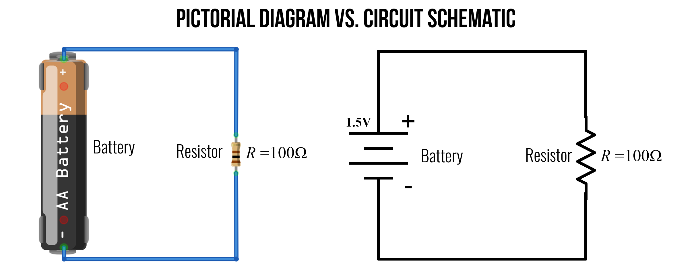
L2: circuit schematics - physical computing
The resistors in the following image are not in parallel. ... Properties of resistors in parallel ... Here is a circuit with resistors in parallel.
Circuits: one path for electricity - lesson - teachengineering
The following diagram shows resistors in a circuit. Get the answers you need, now! mely56 mely56 07/15/2019 Physics Middle School answered The following diagram shows resistors in a circuit. 1 See answer Advertisement Advertisement mely56 is waiting for your help. Add your answer and earn points. glenpricejr033 glenpricejr033 Answer:
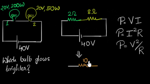
Solved example: power dissipated in bulbs
In the following resistors in parallel circuit the resistors R 1, R 2 and R 3 are all connected together in parallel between the two points A and B as shown. Parallel Resistor Circuit In the previous series resistor network we saw that the total resistance, R T of the circuit was equal to the sum of all the individual resistors added together.

The circuit in the diagram consists of a battery with emf e ...
If you follow the circuit diagram from one side of the cell to the other, you can only pass ... This is why our homes are wired up with parallel circuits.

4.1 resistors in series and parallel | texas gateway
Resistors in Series. Resistors are said to be in series whenever the current flows through the resistors sequentially. Consider , which shows three resistors in series with an applied voltage equal to Since there is only one path for the charges to flow through, the current is the same through each resistor. The equivalent resistance of a set of resistors in a series connection is equal to the ...
Untitled
The resistors in a series circuit can be interchanged without affecting the total resistance, current, or power to each resistor or the circuit. In the next tutorial about Resistors, we will look at connecting resistors together in parallel and show that the total resistance is the reciprocal sum of all the resistors added together and that the ...

Ncert class 10 science lab manual - resistors in series ...
Combination series/parallel circuits – troubleshooting motors ...
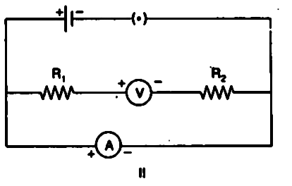
In an experiment to determine equivalent resistance of two ...
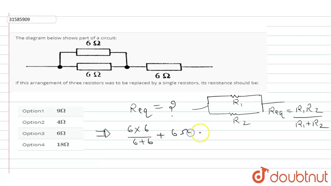
The diagram below shows part of a circuit: if this arrangement of three resistors was to be replaced

Alternating current circuit - an overview | sciencedirect topics
10.3: resistors in series and parallel - physics libretexts

Q7. the given circuit diagram shows the experiment ...

Physics reference: may 2017

The following diagram shows resistors in \_\_\_ and is \_\_\_\_ o

Lakhmir singh physics class 10 solutions for chapter 1 ...
Circuits: one path for electricity - lesson - teachengineering

Series rlc circuit and rlc series circuit analysis

Resistors in parallel - parallel connected resistors
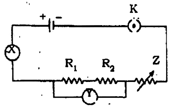
The given circuit diagram shows the experimental arrangement ...

4.1 resistors in series and parallel | texas gateway
0 Response to "33 the following diagram shows resistors in and is of the arrangement of circuit elements in homes."
Post a Comment