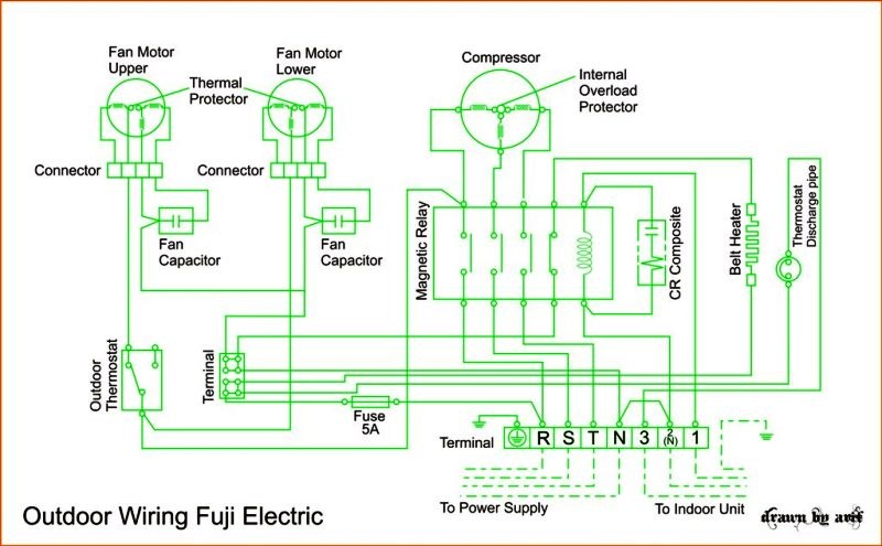
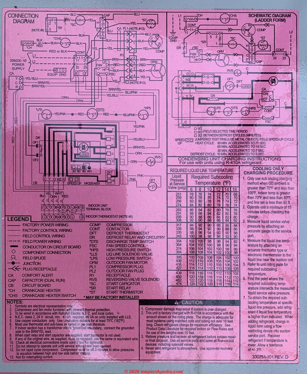
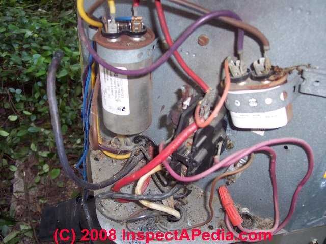
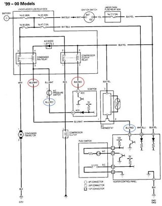
34 ac condenser wiring diagram
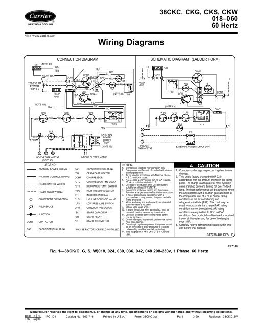
Ac Compressor Wiring Diagram - wiring diagram is a simplified satisfactory pictorial representation of an electrical circuit. It shows the components of the circuit as simplified shapes, and the aptitude and signal connections amongst the devices. A wiring diagram usually gives suggestion very nearly the relative slope and deal of devices and ... Diagram courtesy of Emerson New techs have a common question of how to wire a condensing fan motor for 3 vs. 4 wires. Jesse Grandbois submitted this tech tip to help make it simple. Thanks, Jesse! This tech tip is a quick one on the difference between wiring universal condenser fan motors and why brown […]
Midea Heating & Air Conditioning ... Outdoor Unit Wiring Diagram for A/C Systems(208/230V 1P 60Hz). CC. COMPRESSOR CONTACTOR. RC 1. RUN CAPACITOR 1.3 pages
Ac condenser wiring diagram
1- Importance Of Electrical Wiring For Air Conditioning Systems. In the detailed design phase, the electrical designer must size and select the wires/cables, conduits, starters, disconnects and switchgear necessary for supplying power and control to HVAC equipment. This information designed by the electrical designer will be and must appear on ... Compressor wiring diagram. A wiring diagram is a simplified traditional photographic depiction of an electric circuit. The standard 220 volt wiring for an air compressor includes no polarity for the red and the black wire so you cannot wire them backwards. The disconnect switch should be a 220 volt 2 pole type for both circuit wires. Inside the air handler unit, the high voltage wiring powers the indoor fan, the heater and provide power for the transformer. Inside the condenser/evaporator unit, the high voltage wiring powers the outside fan and the compressor. 3- Low voltage control part: This part has (2) mode for operation which are:
Ac condenser wiring diagram. The heat pump condenser fan motor will not. The wiring for the heat pump condenser fan motor will be slightly different. The black wire (noted in the wiring diagram) will likely be terminated on a control board. This control board is the defrost control board. It also controls the condenser fan motor in a heat pump. When a heat pump goes into ... Collection of air conditioner wiring diagram pdf. A wiring diagram is a streamlined standard photographic depiction of an electric circuit. It shows the parts of the circuit as streamlined shapes, and the power and also signal connections in between the gadgets. Nov 27, 2019 - Ac Condenser Fan Motor Wiring Diagram 4 Wire Beautiful For New 7 Air Compressor Wiring Diagram - air compressor capacitor wiring diagram, air compressor starter wiring diagram, air compressor wiring diagram, Every electrical structure consists of various different parts. Each component should be placed and connected with other parts in specific way. If not, the arrangement won't function as it should be.
The condenser is one of three crucial parts of a home air conditioning system. It is the component responsible for actually releasing the heat collected by the evaporator inside the home. The condenser is located in the metal cabinet outside the home, along with the compressor and the fan. The third critical component, the evaporator, is ... This is how to wire a 240-volt single-phase Condenser used for Air Conditioning. This includes where to install the high and low voltage wiring and why, how ... Since the #2 white wire is allways connected to the fan and compressor, since it Air conditioning works the same no matter what the applicatiion. auto, home, . "My original condenser fan motor has three wires and the replacement the following guide: HVAC Condenser Fan Motor Wiring Diagram. Thermostat Wiring Diagrams Quality Hvac Guides 101. I Need A Basic Wiring Diagram For An Old Ruud Heat Pump Air Handler T Stat My System Has Been Complete Disconnected And. Rheem Ruud Condenser Fan Motor 51 23055 11 Wiring Diagram. Thermostat Wiring Guide For Homeowners 2021. Wiring Diagram Ruud Rqpm A036jk000aua Rqrm A060jk000aua.
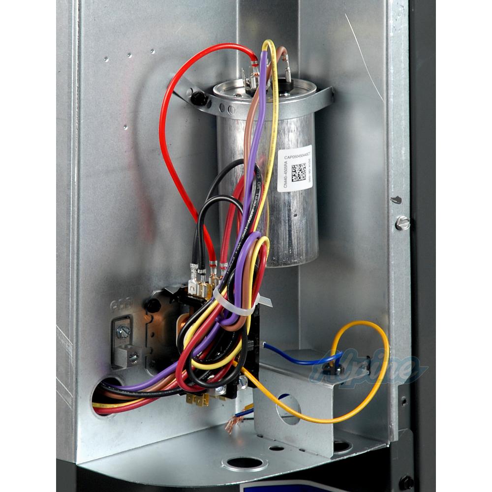
For a visual picture of typical wiring configurations, reference the following guide: HVAC Condenser Fan Motor Wiring Diagram. Finally, this guide is intended to be used as a general overview of common condenser unit wiring schematics. Some condenser fan motors wire to a circuit board while others use proprietary plugs for their connectors. Ac Condenser Wiring Diagram - ac condenser contactor wiring diagram, ac condenser fan motor wiring diagram, ac condenser fan wiring diagram, Every electric arrangement consists of various different components. Each component should be set and linked to different parts in specific manner. If not, the arrangement won't function as it should be. The wiring diagram identifies the fan motor and compressor s wire colors and functions. However some people still struggle with the wiring part of the motor to the capacitor. Compressor Start Capacitor Wiring Diagram Diagrams Schematics For Starting Thermostat Wiring Circuit Diagram Ac Wiring Finally this guide is intended to be used as a general … Nordyne Air S1BA condenser wiring diagram. Nordyne Air Conditioner AGGA1. 1 Solutions. FS5BDK wiring diagram Nordyne Air Conditioner Model T3BAK and B1B. I need a ac fan capacitor for a Nordyne model FS5BDK. I, 7/3/ 2 weeks. Give, 5/15/ I have a Nordyne Model S3BAK Serial# S3B The, 5/13/ We are looking for a wiring diagram for a nordyne, 5/7 ...
Wiring Diagram Ac Window In 2021 Diagram Hvac Tech Air Conditioner . Tecumseh How To Re Wire Relay For Compressor In 2021 Air Compressor Pressure Switch Ac Condenser Compressor . Perfect Wiring Diagram For 220 Volt Air Compressor Three Phase Air Compressor Wiring Diagram Trusted W Air Compressor Pressure Switch Air Compressor Compressor
The question is: How to Wire an Air Conditioner for Control 5 Wires - The diagram below includes the typical control wiring for a conventional central air conditioning system.Furthermore, it includes a thermostat, a condenser, and an air handler with a heat source. Moreover, the heat source for a basic ac system can include heat strips for electric heat or even a hot water coil inside the ...
55 New Potential Relay Wiring Diagram- A govern relay is used in the automotive industry to restrict and regulate the flow of electricity to various electrical parts inside the automobile. They permit a small circuit to direct a later flow circuit using an electromagnet to rule the flow of electricity inside the circuit.
Wiring Diagram for A Air Conditioner Run Capacitor - wiring diagram is a simplified suitable pictorial representation of an electrical circuit. It shows the components of the circuit as simplified shapes, and the gift and signal friends amongst the devices. A wiring diagram usually gives instruction just about the relative face and covenant ...
Basic Compressor Wiring - Youtube - Ac Condenser Wiring Diagram. Wiring Diagram arrives with numerous easy to adhere to Wiring Diagram Instructions. It's meant to aid all the common user in creating a proper program. These directions will be easy to grasp and use. With this manual, you will be in a position to determine how each and every ...
Compressor S R C Move the brown wire from the "F" ... 208-230 VAC L1 L2 208-230 VAC L1 L1 Common L2 L2 L2 Brown (Common) Title: HVAC-Condenser-Fan-Motor-Wiring-Diagram Author: xdxg012 Created Date: 5/24/2018 11:26:51 AM ...
Quick video stepping you through how to wire a typical 220v AC condenser unit. Hope it helped you out! Please subscribe!Blessings,Ben
How to wire an air conditioner for control 5 wires the diagram below includes the typical control wiring for a conventional central air conditioning systemit includes a thermostat a condenser and an air handler with a heat source. Straight cool air conditioning condensing unit wiring practice. If not the arrangement wont function as it should be.
Hvac Low Voltage Wiring Furnace Rheem Classic 90 Updraft Frigidaire Fs3ba 036ka Mengomel Kasar. Rheem ruud hvac age manuals parts connecting thermostat on heat diagram ac wiring full dual compressor condensing unit condenser fan motor 51 23053 air conditioner pump faqs for control 5 wires new contactor diy old handler resources how to wire low voltage question conditioners and pumps chart room ...
Standard A/C Condenser AC Contactor 4 This diagram is to be used as reference for the low voltage control wiring of your heating and AC system. Always refer to your thermostat or equipment installation guides to verify proper wiring. NOTE Some AC Systems will have a blue wire with a pink stripe in place of the yellow or Y wire.
Description : Condenser Fan Motor Wiring Diagram in Ac Condenser Fan Motor Wiring Diagram, image size 600 X 559 px, and to view image details please click the image. Here is a picture gallery about ac condenser fan motor wiring diagram complete with the description of the image, please find the image you need.
Standard A/C Condenser AC Contactor 4 This diagram is to be used as reference for the low voltage control wiring of your heating and AC system. Always refer to your thermostat or equipment installation guides to verify proper wiring. NOTE Some AC Systems will have a blue wire with a pink stripe in place of the yellow or Y wire.
Ac Condenser Wiring Diagram Ac Condenser, Air Conditioning System, ... Ac Condenser Fan Motor Wiring Diagram 4 Wire Beautiful For New 7 | Car Wiring Diagram.
Inside the air handler unit, the high voltage wiring powers the indoor fan, the heater and provide power for the transformer. Inside the condenser/evaporator unit, the high voltage wiring powers the outside fan and the compressor. 3- Low voltage control part: This part has (2) mode for operation which are:
Compressor wiring diagram. A wiring diagram is a simplified traditional photographic depiction of an electric circuit. The standard 220 volt wiring for an air compressor includes no polarity for the red and the black wire so you cannot wire them backwards. The disconnect switch should be a 220 volt 2 pole type for both circuit wires.
1- Importance Of Electrical Wiring For Air Conditioning Systems. In the detailed design phase, the electrical designer must size and select the wires/cables, conduits, starters, disconnects and switchgear necessary for supplying power and control to HVAC equipment. This information designed by the electrical designer will be and must appear on ...






0 Response to "34 ac condenser wiring diagram"
Post a Comment