34 fire alarm tamper switch wiring diagram
Box Tamper Switch This switch provides tamper protection for the main control panel in case of unauthorised access. ... Popular SAB Wiring Diagrams ... If activated they will cause a unique alarm with a distinctive 'Fire' tone on the internal speaker. In addition, the external sounder will be pulsed rather than sounding continuously in ...
Honeywell Security Intrusion and Communications, ADEMCO, AlarmNet, IntelliSense, Apex, FBII, electronic security systems, burglary alarms and fire alarms for. Installation manual for the Honeywell wireless three-zone sensor. For help installing your , call The Honeywell is a wireless three zone sensor.
MultiTransmitter User Manual. Updated October 4, 2021. MultiTransmitter is an integration module with 18 wired zones for connecting third-party detectors to the Ajax security system. To protect against dismantling, MultiTransmitter is equipped with two tampers. It is powered from the mains 100-240 V AC, and can also run on a 12 V backup battery.

Fire alarm tamper switch wiring diagram
How it works. The basic principle, when a human or warm-blooded animal comes to a radius of about 3 to 5 meters. This circuit detects infrared radiation from theirs and sends an alarm. See the circuit diagram below. When a signal from an Infrared PIR Sensor module comes to the circuit. It is a 3V peak voltage.
MultiTransmitter Fibra User Manual. MultiTransmitter Fibra is an integration module with 18 wired zones for connecting third-party detectors and devices to the Ajax security system. Supports NC, NO, EOL, 2EOL, and 3EOL devices. MultiTransmitter Fibra is equipped with two tampers that protect against lid opening and detaching from the surface.
Step 3: Refer to the diagram on the product page for Dec 17, 2019 - Basic Fire Alarm in Home. 1967-69 Firebird/Camaro/Trans-Am. Wireless fire alarm systems are an effective alternative to traditional wired fire alarm systems for all applications. 5L1984 Pontiac Fiero 4-151 2. 2 allows a monthly test frequency electric fire pumps not identified ...
Fire alarm tamper switch wiring diagram.
Mercury outboard kill switch wiring
Fire Suppression Flow and Tamper Switches. Field test all tamper and flow switch fire suppression devices. Initiate the tamper switch by rotating the position of ea ch fire protection valve. Verify each magnetic is dropped and the door is released. Fire Alarm Notification Devices
short as practical. See attached wiring diagram for more info. Fire alarm control unit (FACU) is powered up and clear of alarms, supervisory signals, and trouble conditions. Have ground fault put on any alarm initiating or notification appliance (horn-strobe) circuit. FACU must indicate "ground" and general "trouble."
Reports fire, burg, and status messages via the Int ... he Wall Tamper screw. 3. After all wiring is complete and the unit is powere d up and the battery is connected, attach the ... Please check that the tamper switches on expander a nd other modules are not being triggered.
A built-in cover tamper switch is activated when the cover is removed. Seller does not represent that the product s it sells may not be compromised or circumvented; that the product s will prevent any personal injury or property loss by burglary, robbery, fire or otherwise; or that the product s will in all cases provide adequate warning or ...
Installation locations and wiring methods shall be in accordance with the National Electrical Code, ANSI/NFPA 70. Do not connect to a receptacle controlled by a switch. Use of a UL listed computer. Use of UL listed readers (Wiegand 26 and 34 bits, stripe 26 and 34 bits, XSF 39 bits have been tested and found to comply).
WARNING: Connecting the Switch wire terminal to any other supply conduc-tor may result in damage to the alarm, failure to operate or shock hazard and void the warranty of the alarm. EXAMPLE OF MULTIPLE ALARM WIRING / ISOLATION UNIT WIRING 5. INSTALLATION LOOP 1 9V A SW N LOOP 2 9V A SW N YELLOW RED WHITE BLUE ORANGE YELLOW RED WHITE BLUE ORANGE ...
Desember 31, 2020. Download Texecom alarm panel wiring diagram Images Library Photos and Pictures. Recent posts 3recentpost list tags 2 way wiring diagram for a light switch 2 wire ceiling fan capacitor wiring diagram. Wiring diagram of ceiling fan with regulator. Texecom Panel Wiring Diagram.
NOTE: Refer to the diagram on page 5, and to the Wiring Diagram on the inside of the back cover of this manual for wiring and component identif ication. 1. Remove knockouts from cabinet to accommodate the power input wires, and wiring to the fire panel. Then mount the cabinet securely to the wall using 4 screws or bolts.
Disengage the supplied mounting plate from the unit by inserting the blade of a small screwdriver into the locking tab release window see Diagram 2 and pressing it against the case locking tab see Diagram 1 while sliding the plate downward along the aademco back. Surface wiring should enter via the thin "breakout" area provided in.
Manual verifone vx510 point transaction systems oy vanha nurmijärventie 62 d. To help with installation and configuration of the verifone pos device. Run an adding machine tape of the transactions. Place all transaction receipts in sequence number order.
Fire alarms can work fine with either style of switch. Fire alarm systems deal with alarm events, tamper events, and supervisory events (sometimes there's no distinction between the latter two). Events cause notifications; virtually all events cause a signal to be transmitted to the monitoring service.
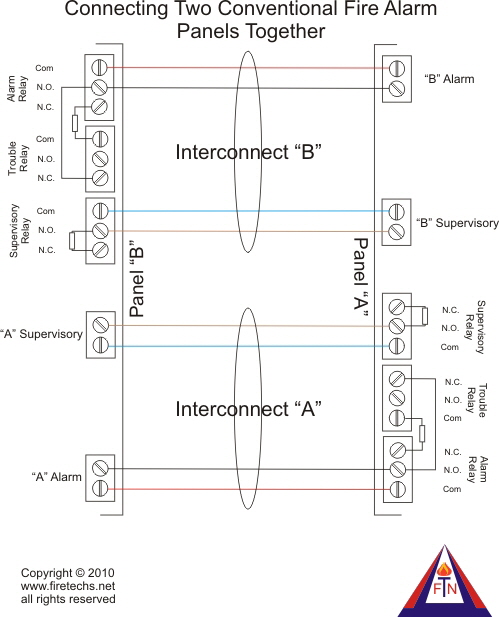
Diagram Fire Alarm Wiring For A B Full Version Hd Quality Forexdiagrams Oct 20, 2021 · How the wires connect from the fire alarm panel. what is a fire alarm system a fire alarm system is a mechanism of substitute substitute interconnected devises and components used to nimble us in proceedings court case of emergency especially fire to protect ...
manual pull station (48" aff unless noted otherwise) water flow switch valve supervisory (tamper) switch door hold open module. provide fire alarm listed hold-open assembly if not called out in door hardware schedule. electric bell for water flow. install at 9'+/- above finished grade or as directed by fire marshal. fire service or emergency phone station station, 'x' denotes type: j = jack h ...
Fire Alarm Tamper Switch Wiring Diagram : Intro To... Leaking Car Ventilation System Diagram - Car A C R... Grove Pi Electric Circuit Diagram - Get Started Wi... Jumpking Jk1418C2 14Ft Combo Orbounder Owner's Man... Craig Ctft716N Owner's Manual / Top 9 Craig Electr... Dorel Home Furnishings 4108629 Owners Manual : Emb...
House Alarm System Circuit Diagram. Amarante Pruvost. July 28, 2021. A wiring diagram is a simplified conventional photographic depiction of an electrical circuit. This is the circuit diagram of car audio system anti theft security which can be effectively used to protect and secure your expensive car audio system from stealing.
3. see plans for location and quantities of fire alarm devices. all horn and strobes shall be wired on alternate circuits. 4. all wiring to fire alarm devices shall be teflon coated approved for fire alarm system. run #14awg minimum exposed in accessible ceiling area. otherwise run in 3/4" emt conduit. 5.
The John Browning-designed Winchester Model 18 94 is the most pre valent of the Winchester lever action repeating rifles. Though initially it was too expensive for most shooters, the Model 18 94 went on to become one of the best-selling hunting rifles of all time—it had the distinction of being the first sporting rifle to sell over one million units, ultimately selling over seven million ...
The LifeSafety Power FPO150-B100D8PE4M1 is an Eight Door Power Supply with Power Distribution and an Enclosure. The kit is configured with space to add backup battery and utilizes an FPO power supply to generate 24VDC and a B100 to generate 12VDC. It includes a locking eight door enclosure with tamper, power supply and wiring speed kit.
Fire Alarm System Wiring Diagram 10 Addressable Car Harness New Fire Alarm System Fire Alarm Alarm Systems For Home . Water Well Pressure Switch Wiring Diagram Gooddy Org New Webtor Me And Submersible Well Pump Deep Well Pump Submersible Pump . 16 Hunter Src Wiring Diagram In 2020 Sprinkler Repair Diagram Electrical Wiring Diagram
XR2B Installation Instructions (pdf) The XR2B is a removal and replacement tool for current models of the 100 and 200 series plug-in smoke detectors. Mounting Bracket for 800 Series Detector Wiring Diagram For 800 Series Detector System Sensor Headquarters 3825 Ohio Avenue St. Charles, IL 60174.
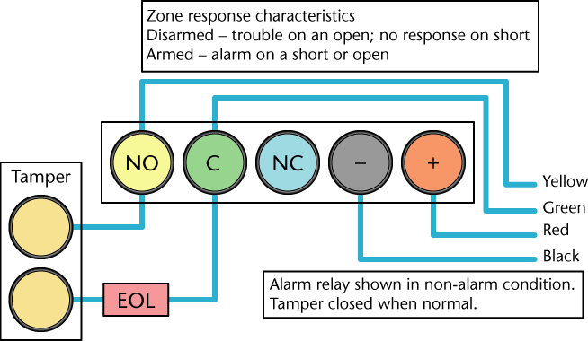
A tamper or 24 hr circuit consists of a pair of tamper cores in the alarm cable and momentary tamper switches in sensors, the alarm panel, junction boxes and sounders. These switches are maintained in a closed position by lids/covers on sensors and other components of the system.
Jun 02, 2013 · The Tamper input (TAMP/COM) should be shorted or connected to a Tamper switch to prevent a Tamper alarm. Comfort can identify which slave or keypad caused a tamper alarm. Turn on power to Comfort. This supplies power to all the other modules connected to Comfort. The quide will be continued in the next section to show what happens after power on
Variety of fire alarm flow switch wiring diagram. A wiring diagram is a streamlined conventional pictorial representation of an electric circuit. It shows the elements of the circuit as simplified shapes, as well as the power as well as signal links between the devices.
Victaulic tamper switch wiring diagram. 2 wire or 4 wire pull stations waterflow devices tamper switches and other normally open contact devices. When installing victaulic couplings the nuts must be tightened evenly to obtain metal to metal contact at the bolts pads. The supervisory switch contains two single pole double.
Transmitter wiring diagram. Connect the status output of the gate/barrier controller to the tamper or alarm terminals of Transmitter. The algorithm of work depends on this. When connected via Transmitter tamper terminals, the security system notifies about opening
The LifeSafety Power FPO150-B100C8PD8PE4M1 an Eight Door Power Supply with Power Distribution and an enclosure. The kit is configured with space to add backup battery and utilizes an FPO power supply to generate 24VDC and a B100 to generate 12VDC. It includes a locking eight door enclosure with tamper, power supply and wiring speed kit.









0 Response to "34 fire alarm tamper switch wiring diagram"
Post a Comment