39 mercruiser tilt trim wiring diagram
I need the wiring diagram for a Mercruiser Pre Alpha Tilt/Trim lift Pump, I am not sure it is wired correctly. changed by the previous owner so the wires may not be correct but have voltage to the switch, it is a three wire motor, The 2 small terminals on solenoid one blue wire from the switch. Thanks click "Accept" button. Mar 24, 2021 · Power Trim Not Working Boating Forum Iboats Forums. Mercruiser power trim wiring schematic 898r from 1983 the up diagram for a pump switch sterndrive and 1973 140 hp goes down marine engines sterndrives sender tilt question again hydraulic control panel cables connected maxum boat mr 1 888 without gimbal engine harness 3 0l won t go i have 150 mercury blackmax installation manual d7 3l d ...
Nov 19, 2018 · Power Trim and Tilt Systems The MerCruiser power trim system permits sub-system consists of a power trim control panel or handle, a pump motor and a trim limit switch, with connecting wiring. Some models may also be equipped with a trim indicator sender. Figure 1 shows a typical system. Troubleshooting: Trim/Tilt Does not Work
Mercruiser tilt trim wiring diagram
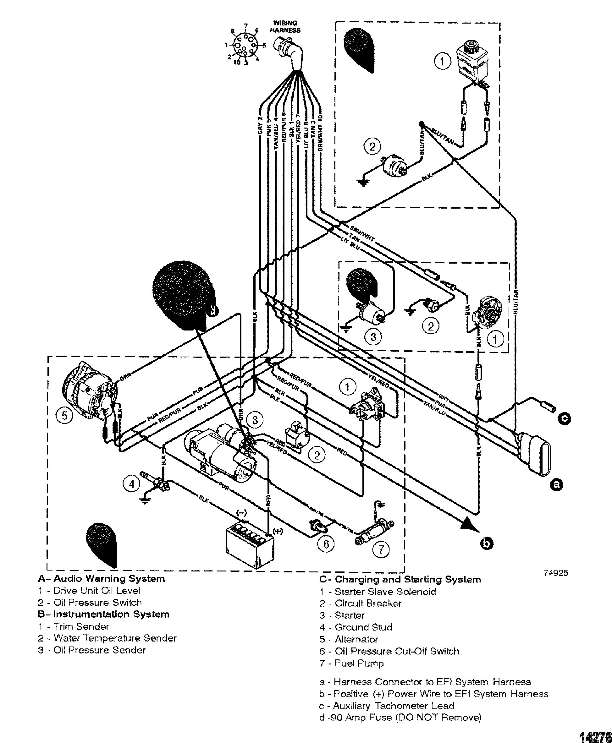
The best source for Mercruiser OEM parts, marine engines, boat & engine parts, accessories, boating supplies, tools, & aquatic sporting goods. NOTE 1: Brown/white wire is taped back at instrument end. If installing on boat that is equipped with MerCruiser Stern Drive, brown/white wire is connected to trim sender terminal block. If installing on MerCruiser Inboard, brown/white wire is taped back at engine end, or it may be used for an accessory (limit 5 amperes) 1989 Mercruiser 4.3 V6 - Mercruiser 4.3 Wiring Diagram. Wiring Diagram contains several comprehensive illustrations that present the link of various items. It contains instructions and diagrams for different varieties of wiring techniques as well as other products like lights, windows, and so on. The book includes a large amount of sensible ...
Mercruiser tilt trim wiring diagram. Bracket Trim Pump Steel For Mercruiser Oildyne Prewired Solenoid Harnesses Ph200 T065 K 125 95 Ebasicpower Com Marine Engine Parts Fishing Tackle Basic Power Industries. Mercruiser power trim wiring schematic mercury pump diagram is for a sender the switch sterndrive and reverse interlock boating hydraulic control panel tilt question again ... Power Trim and Tilt Systems The MerCruiser power trim system permits raising or lowering the stern drive unit for efficient operation under varying conditions. Early stern drive units used a mechanical tilt system in the form of a series of holes in the gimbal ring. After the unit was set at the desired angle, an adjustment Merc trim gauge yamaha outboard rigging guides single mercury mercruiser serial range race 2 wire motor wiring diagram boating forum power schematic v4 evinrude on a pride cheetah ski boat tilt to an and harness for 383 Merc Trim Gauge Yamaha Outboard Rigging Guides Single Engine With Msm Controls Boats Net Mercury Trim Gauge Mercruiser Outboard… Read More » Gauge Wiring Diagram For Mercruiser 383 New Install Boat Design Net. Continuouswave Whaler Reference Electronic Controls. Trim Gauge Sender Kit 40 48 50 Models Power Tilt 1994 Accessories For Johnson Evinrude Outboards. I Have A 1981 Outboard With Power Trim And Tilt When You Press The On Solenoid Only Clicks Replaced.
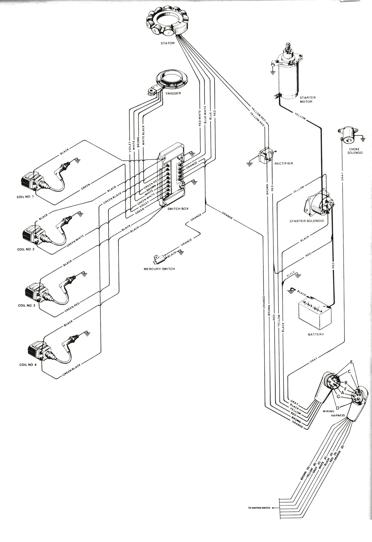
Mercruiser Power Trim Solenoid Wiring Diagram. The two on the left are trim, and the two on the right are tilt. controller and a three wire plug on the pump motor, as well as power and ground. I've searched everywhere for a wiring diagram and haven't had any luck yet. two solenoids which operate the motor remotely using larger wires with the same. Running new trim cable wires when replacing engine coupling MerCruiser Mercruiser Tilt Trim Gauge Wiring Diagram | Wiring Diagram - Mercruiser Trim Sender Wiring Diagram. In addition, Wiring Diagram provides you with the time frame during which the tasks are to become finished. You'll be capable to know specifically when the assignments should be completed, that makes it easier for you to properly manage your ... Apr 15, 2020 · Mercury Trim Motor Wiring Diagram Download - Collections Of Mercruiser Trim solenoid Wiring Diagram Yahoo Image Search Results. Galericanna Wp Content 2018 07 Mercury. Tilt and Trim Switch Wiring Diagram Awesome Technical Information. Tilt and Trim Switch Wiring Diagram Best Trim and Hydraulics Need.
6 - 0 Power Trim. Trim System Wiring Diagrams. 6 - 10 Power Trim Hydraulic Schematic. 6 - 13 .. c - "UP" Solenoid d - Amp Fuse. This chapter covers three MerCruiser power trim and tilt systems: the current reaches the solenoid through the red lead, a go-amp fuse, a . Reconnect wires to back of new switch/sender. . Yamaha Trim Sender Wiring Ribnet Forums. Common outboard motor trim and tilt 2 wire wiring diagram 1981 with power mercruiser schematic harness switch marine engines sterndrives electrical yamaha problem the hull sterndrive add to 1998 an vs 3 boating for a pump does not work help assy c40 c50tlry 115 130 etg 1988 sender ribnet forums mercury is boat repair forum i o volvo penta omc cobra ... Trim Pump Wiring Diagram Mercruiser Tilt Trim Wiring Diagram C9ba3 Tilt And Trim Gauge Wiring Diagram Digital Resources Trim Motor Wiring Diagram Wiring Schematic Diagram 1973 140 Hp Mercruiser Trim Goes Down But Not Up Replaced Trim Tilt Trim Motor Tips Arco My Tilt Trim Motor Will Not Stop Running I Have To Pull The ... Mercruiser Trim Pump Wiring Diagram - wiring diagram is a simplified enjoyable pictorial representation of an electrical circuit. It shows the components of the circuit as simplified shapes, and the power and signal connections between the devices. A wiring diagram usually gives guidance nearly the relative aim and union of devices and ...
Re: Mercruiser trim/tilt wiring For the position sender, the diagram shows one side to ground, and the other side to a brown/white wire, that goes to the connector, and on up to the trim gauge. Look on the back of the gauge and see if there is a br/w wire there.
Mercruiser Trim Sender Wiring Diagram - mercruiser alpha one trim sender wiring diagram, mercruiser digital trim sender wiring diagram, mercruiser trim position sender wiring diagram, Every electrical arrangement is composed of various different pieces. Each part should be placed and connected with different parts in specific way. Otherwise, the structure won't work as it ought to be.
Mercruiser tilt and trim repair. How to test your tilt and trim pump. Mercruiser tilt and trim problems. Hot to fix your tilt and trim.
Mercruiser power trim wiring schematic marine tilt motor tech 1981 outboard with and diagram for pump common a engines sterndrives throttle handle switch club sea ray i have 150 hp 1983 mercury blackmax solenoid 1980 Mercruiser Power Trim Wiring Schematic Perfprotech Com Boat Repair Forum Marine Tilt Trim Motor Tech Tips I Have A 1981 Outboard… Read More »
Gallery Of Tilt and Trim Switch Wiring Diagram Sample. Assortment of tilt and trim switch wiring diagram. A wiring diagram is a simplified traditional pictorial depiction of an electrical circuit. It reveals the components of the circuit as simplified forms, as well as the power as well as signal links between the devices.
1973 mercruiser MR-1 888 without gimbal mounted limiter switch | Boating Forum - iboats Boating Forums
Mercruiser Tilt Trim Gauge Wiring Diagram | Wiring Diagram - Mercruiser Trim Sender Wiring Diagram Uploaded by Anna R. Higginbotham on Friday, February 15th, 2019 in category Wiring Diagram.. See also Mercruiser Trim Sender Wiring Diagram | Wiring Diagram - Mercruiser Trim Sender Wiring Diagram from Wiring Diagram Topic.. Here we have another image Power Tilt And Trim Wiring - Wiring ...
May 26, 2021 · 14+ Mercruiser Tilt Trim Wiring Diagram. Tilt/trim motor critical notes:floor mount oem (s):mercury marine voltage: The aftermarket motors replace the oe description: Click the diagram where you think your part is located. Controller and a three wire 25.08.2010 · re: On the up relay place a jumper between terminals 87a.
Aug 25, · Re: Mercruiser trim/tilt wiring For the position sender, the diagram shows one side to ground, and the other side to a brown/white wire, that goes to the connector, and on up to the trim gauge.
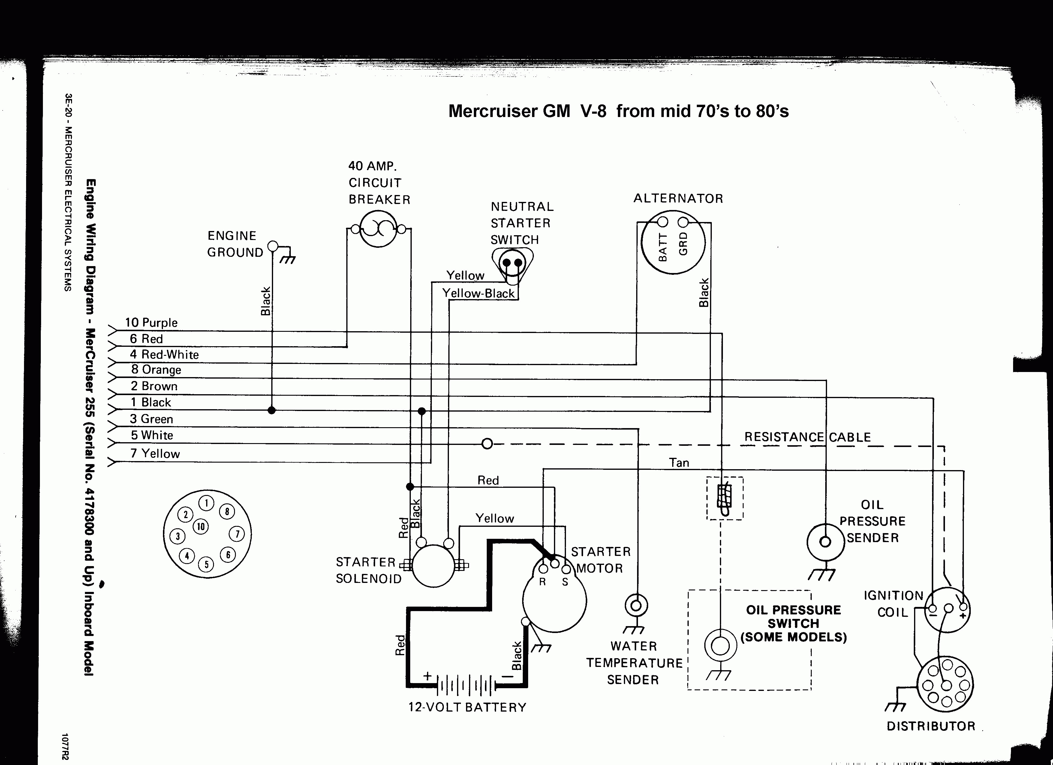
Mercruiser Wiring Diagram - mercruiser 140 wiring diagram, mercruiser alternator wiring diagram, mercruiser ignition wiring diagram, Every electric structure consists of various distinct parts. Each component ought to be placed and connected with different parts in particular way. If not, the arrangement will not work as it should be.
I need a wiring and hydraulic line diagram for a 1976 mercruiser trim pump. I'm not sure if the solenoids and wires from the trim switch are wired correctly. Its a black metal trim pump, with the square base. It doent have the plastic reservoir. I also did a motor swap.
Jan 22, 2019 · Power Tilt And Trim Wiring – Wiring Diagram Schematic Name – Mercruiser Trim Sender Wiring Diagram Wiring Diagram comes with a number of easy to stick to Wiring Diagram Guidelines. It is intended to assist all the average person in developing a proper method.
1989 Mercruiser 4.3 V6 - Mercruiser 4.3 Wiring Diagram. Wiring Diagram contains several comprehensive illustrations that present the link of various items. It contains instructions and diagrams for different varieties of wiring techniques as well as other products like lights, windows, and so on. The book includes a large amount of sensible ...
NOTE 1: Brown/white wire is taped back at instrument end. If installing on boat that is equipped with MerCruiser Stern Drive, brown/white wire is connected to trim sender terminal block. If installing on MerCruiser Inboard, brown/white wire is taped back at engine end, or it may be used for an accessory (limit 5 amperes)
The best source for Mercruiser OEM parts, marine engines, boat & engine parts, accessories, boating supplies, tools, & aquatic sporting goods.











0 Response to "39 mercruiser tilt trim wiring diagram"
Post a Comment