34 yamaha 703 remote control wiring diagram
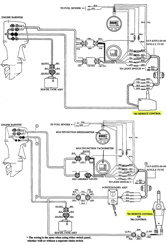
If you set sights on to download and install the 703 engine control system diagram, it is definitely easy then, past currently we extend the connect to purchase and create bargains to download and install 703 engine control system diagram hence simple! Yamaha 703 control safety kill switch wiring issues Reversing a Yamaha 703 forward control ... Yamaha 703 remote control box wiring diagram. There are 4 individual wires coming out of yamahas 703 control box terminated with bullet connectors. With a 704 yamaha remote control box binnacle mount. The original harness was cut and i am installing it on a pontoon with no gauges but engine and control both are set up for power tilt and trim.
Variety of yamaha 703 remote control wiring diagram. A wiring diagram is a simplified traditional pictorial depiction of an electrical circuit. It shows the elements of the circuit as simplified shapes, as well as the power and signal connections in between the devices.

Yamaha 703 remote control wiring diagram
View and Download Yamaha 703 instructions manual online. Side Mount Remote Control. 703 remote control pdf manual download. I bought the boat used and someone has already been inside the controls cutting on wires so that the boat functions without the kill switch. You can pull out... As stated earlier, the lines in a Yamaha 703 Remote Control Wiring Diagram signifies wires. Occasionally, the cables will cross. However, it doesn’t imply connection between the wires. Injunction of 2 wires is usually indicated by black dot to the intersection of 2 lines. There will be principal lines which are represented by L1, L2, L3, and so on.
Yamaha 703 remote control wiring diagram. Dec 29, 2019 · Yamaha 703 Remote Control Wiring Diagram. Variety of yamaha 703 remote control wiring diagram. A wiring diagram is a simplified traditional pictorial depiction of an electrical circuit. It shows the elements of the circuit as simplified shapes, as well as the power and signal connections in between the devices. Yamaha 703 Remote Control Box Wiring Diagram. By Margaret Byrd | January 1, 2018. 0 Comment. الترجيع حية أكسيد yamaha 703 remote control parts nooutfit com linkedin genuine box push 48207 1a 10 1b 22 00 ft60b bottom line isle of man wiring to helm the hull truth boating and fishing forum la boîte à télécommande extérieure de ... Yamaha 703 control safety kill switch wiring issues Reversing a Yamaha 703 forward control Mansa Yamaha 703 How To Read, Understand, And Use A Wiring Diagram - Part 1 - The Basics Engine Control System, Part 1 Center Console Restoration Part 7: Remote Control ECM Circuit \u0026 Wiring Diagram Outboard Motor Marine Outboards – Yamaha 703 Remote Control Wiring Diagram Wiring Diagram includes many detailed illustrations that show the link of varied products. It contains directions and diagrams for different varieties of wiring methods along with other things like lights, windows, etc.
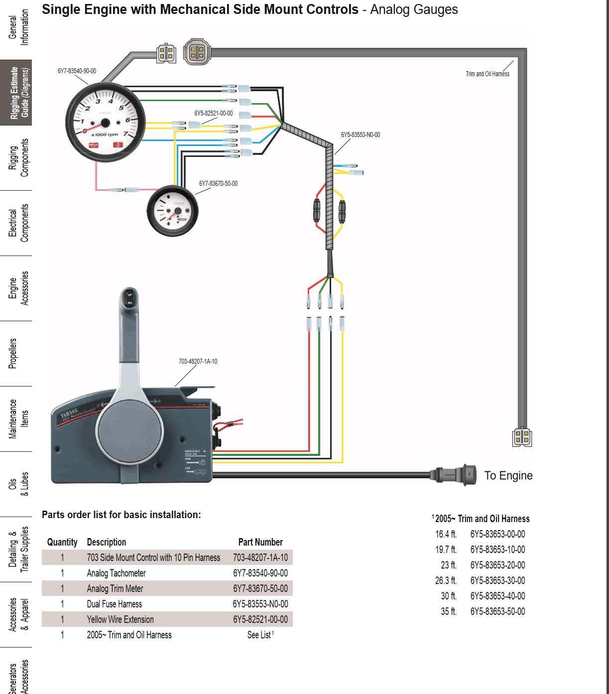
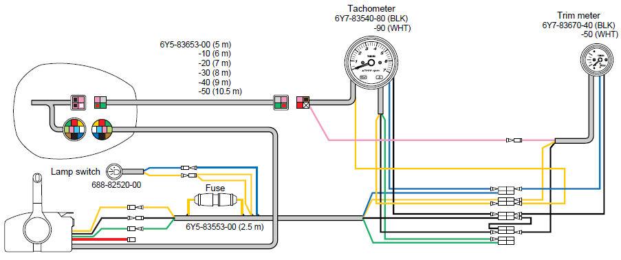
Aug 04, · Re: Yamaha remote control wiring diagram usually 4 wires from that box. yellow is ignition supply to guages, green is tach signal, red is constant 12v for digital speedo memory (wont turn on without it), black is ground. some boxs have no red wire. View and Download Yamaha Outboards operation manual online. Marine Outboards - Yamaha 703 Remote Control Wiring Diagram Wiring Diagram will come with several easy to stick to Wiring Diagram Guidelines. It is intended to aid all the common consumer in developing a correct method. These guidelines will likely be easy to grasp and implement. Jan 15, 2012. #1. I just purchased a new Yamaha 703 remote control box for my aluminum. skiff. There are two bridles of wires coming out of the control box and I'm. not sure how to wire it up. According to the wiring diagram, it looks like one set of wires (double set. of Red, Sky Blue, Lt. Green) are for the trim & tilt. Yamaha 50 Wiring Diagram Wiring Diagram 500 . Yamaha 703 Remote Control Wiring Diagram Carfindernet Com . Chiral Multidentate Oxazoline Ligands Based On . Yamaha 704 Remote Control Wiring Diagram Wiring Diagram . Yamaha 704 Remote Control Service Manual . Help Needed Yamaha Tach Wiring Page 1 Iboats Boating . 688 8258a 10 00 688 8258a 10 Main ...
703 remote control wiring help. I am having to rewire a 703 remote control to my 1987 yamaha etlh 70 hp. the original harness was cut and i am installing it on a pontoon with no gauges----but engine and control both are set up for power tilt and trim. I am on a budget with this project as it is an old pontoon and really don't want to get but so ... May 13, 2019 · 703 Yamaha Remote Control Wiring Diagram 13.05.2019 13.05.2019 0 Comments on 703 Yamaha Remote Control Wiring Diagram There are 4 individual wires coming out of Yamaha's control box, You can also find the wiring diagram for the yamaha control box in this. A 703 Side Control came with a Yamaha outboard engine I bought recently. I am surprised there is no rubber or similar gasket to go between it and the mounting surface. In my case, I am using a supplied spacer and would have thought there should have been one to go between that and the side control. Jan 02, · wiring diagram for a yamaha remote control box for a outboard motor need to know what wirer go were could you - Boating question. Yamaha Wiring Diagram. There are numerous explanation why you are looking for specifics about Yamaha Remote Control Wiring Diagram, and surely, you are looking for new concepts for your diagramweb.net ...
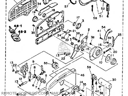
yamaha outboard remote control comp parts 703 diagram and ...
Yamaha 703 Remote Control Wiring Diagram - yamaha 703 remote control wiring diagram, Every electric structure is composed of various unique parts. Each component should be placed and connected with different parts in specific manner. Otherwise, the structure won't function as it should be.
Yamaha control box 703 vs 704
11 Apr 2020 — Hi... I trying to find a wiring diagram/installation manual for a Yamaha 703 Remote. Can anyone help with finding a manual to download ...
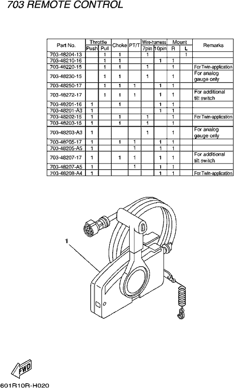
City West Yamaha - _REMOTE CONTROL 2010 - REMOTE CONTROL BOX 2
Yamaha 703 Remote Control Wiring Diagram . Us 120 0 Marine Outboard Remote Control Box Yamaha For Boat Engine With 10 Pin Push To Open On Aliexpress . 36 Volt Golf Cart Wiring Diagram Wiring Diagram . Berbagi. Posting Komentar untuk "Yamaha 703 Remote Control Wiring Diagram"

Yamaha 703 Control Box - problem with re-assembly of box
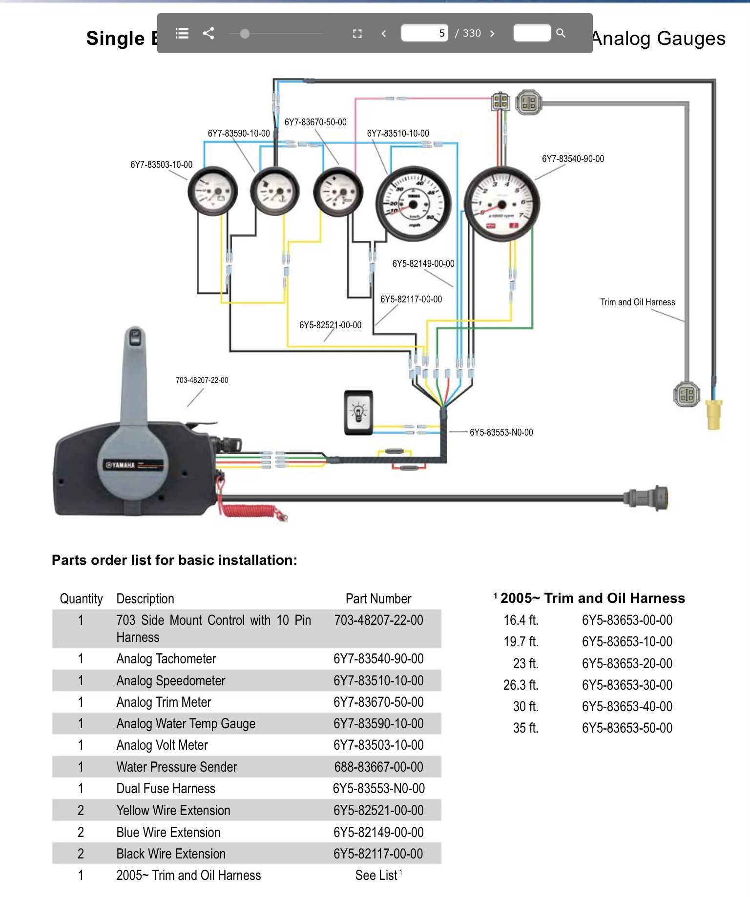
Re: Yamaha 703 remote control wiring diagram usually 4 wires from that box. yellow is ignition supply to guages, green is tach signal, red is constant 12v for digital speedo memory (wont turn on without it), black is ground. some boxs have no red wire. J Johnny Stugots Cadet Joined Apr 10, 2007 Messages 27 Apr 21, 2007 #3

PULL Throttle Remote Control Box 703 for Yamaha Outboard Side ...
Aug 04, · Re: Yamaha remote control wiring diagram usually 4 wires from that box. yellow is ignition supply to guages, green is tach signal, red is constant 12v for digital speedo memory (wont turn on without it), black is ground. some boxs have no red wire. wiring diagram for a yamaha remote control box for a outboard motor need to know what ...
Yamaha Tachometer hook up/wiring ?? - Alaska Outdoors Forums
Yamaha 703 remote control box wiring diagram Dan has been a licensed journey-level electrician for some 17 years. He has extensive experience in most areas of the electrical trade.A "3-way switch" is really two switches that both control one light. This illustration makes it look simple, but this article explains the intricacies of wiring a 3 ...
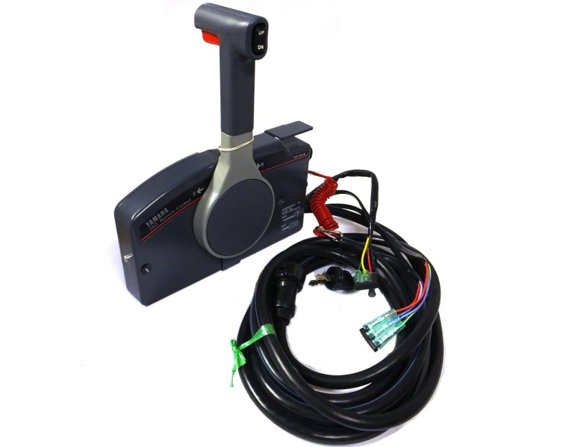
Genuine YAMAHA 703 Remote Control Box 'Push' - 703-48207-1A-10 - 703-48207-1B-10 - 703-48207-22-00
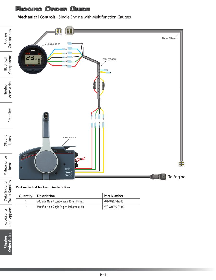
How to install Yamaha 70 hp remote control, shift and throttle cables? 1 of 21. https://amzn.to/31KpWUC - 703-48207-22-00 Side Mount Remote Control Throttle ...

Whaleflo Outboard Remote Control +10 Pin Cable For Yamaha 703 ...
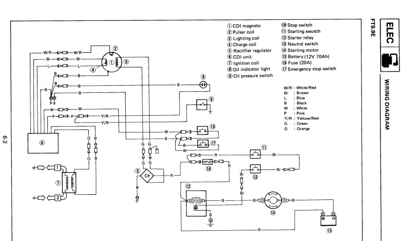
Dave. ASIDE: Does anyone have the manual for a Yamaha 703 remote control? jimh. posted 04-30-2006 11:01 AM ET (US) The usual wiring to a tachometer will have: --switched +12 that follows ignition switch on engine so has voltage in RUN and START positions; --battery negative or common; --tachometer pulses from engine;

Buy Boat Outboard Remote Control Box for Yamaha,OEM 703 Side ...
06-14-2018, 03:10 PM. Damn if I can find out where the pink, black and yellow wires are to go. There is a buzzer inside the 703 to which the pink wire and the yellow wire are connected. Yellow provides voltage to the buzzer when the key is on. The engine provides a ground via the pink wire to cause the buzzer to sound.
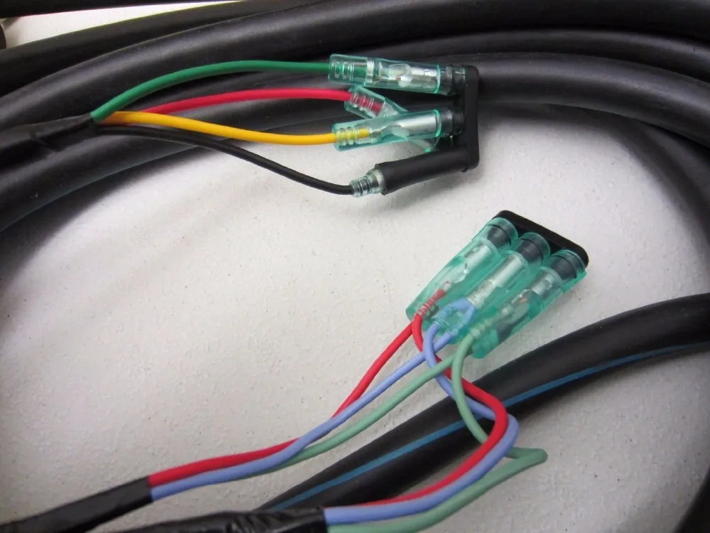
Yamaha 703 remote wiring? I purchased a new boat with an F70 on it with the 703 remote control. Coming out the back of the remote are three pairs of wires with a female bullet connector in each: red with it looks like a light purple stripe, light purple, and light green. They are covered with a rubber plug.

Yamaha 703 Remote Control Installation, Jobs EcityWorks
Mar 12, 2018 - Wiring diagram yamaha 703 remote control Guide to Image Wiring ... yamaha outboard remote control comp parts 703 diagram and parts Car Chloe ...

Electronics box
Topic: Yamaha 703 Side Mount Controller - output wires definition? tedious. posted 07-28-2010 03:29 PM ET (US) There are 4 individual wires coming out of Yamaha's 703 control box, terminated with bullet connectors. Colors of the wires are red, green, yellow, and black. Does anyone have a definition for each wire?
2020 F70 LA wiring diagram needed - The Hull Truth - Boating ...
Yamaha 703 remote control box wiring diagram welcome thank you for visiting this simple website we are trying to improve this website the website is in the development stage support from you in any form really helps us we really appreciate that. Colors of the wires are red green yellow and black.
Yamaha wiring ? - RIBnet Forums
Apr 05, 2019 · Yamaha 703 Remote Control Wiring Diagram. L30cm 10 pin 703 yamaha outboard remote linkedin wiring diagram manual for control to helm the conrol box ribnet rigging 1994 1996 whaleflo premium genuine need help relocating side. L30cm 10 Pin 703 Yamaha Outboard Remote Control Box مصقول.
Tach and wiring - Yamaha Outboard Parts Forum
As stated earlier, the lines in a Yamaha 703 Remote Control Wiring Diagram signifies wires. Occasionally, the cables will cross. However, it doesn’t imply connection between the wires. Injunction of 2 wires is usually indicated by black dot to the intersection of 2 lines. There will be principal lines which are represented by L1, L2, L3, and so on.
Yamaha 703 Remote Control Troubleshooting, Jobs EcityWorks
I bought the boat used and someone has already been inside the controls cutting on wires so that the boat functions without the kill switch. You can pull out...

Yamaha 703 Control- converting pull to push
View and Download Yamaha 703 instructions manual online. Side Mount Remote Control. 703 remote control pdf manual download.
Yamaha 115/130 ETG 1988 parts lists and schematics

Install on Yamaha Outboard – FELL Marine
Jump neutral switch in Yamaha 704 remote box - The Hull Truth ...

IGNITION SWITCH ADAPTABLE REMOTE CONTROL YAMAHA 703-82510-43 ...

Trim Tilt Switch 703-82563-02-00 For Yamaha Engine Outboard ...

2015 outboard Rigging and Parts - Yamaha Outboard Motors ...

Amazon.com: Remote Control Box Ignition Switch/Main Switch ...

GOT STUCK IN MALFUNCTIONING PROBLEM ?... - Boat Propeller TW
Jump neutral switch in Yamaha 704 remote box - The Hull Truth ...
Page 283 of Rigging Parts 2013
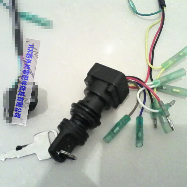
Remote Control Box Ignition Switch / Main Switch Assy 703 ...
2020 F70 LA wiring diagram needed - The Hull Truth - Boating ...

Yamaha 703 remote control problem.
Yamaha control box problem - Page 2 - RIBnet Forums

Amazon.com: 688-8258A-20 Cable Main Wire Harness for Yamaha ...
Outboard Remote Control Box Assy With 7 Pin Cable For Yamaha ...

Do you have the wiring diagram for the gages? F225txrd yamaha ...
0 Response to "34 yamaha 703 remote control wiring diagram"
Post a Comment