35 water treatment plant diagram
Wastewater treatment is a process used to remove contaminants from wastewater and convert it into an effluent that can be returned to the water cycle.Once returned to the water cycle, the effluent creates an acceptable impact on the environment or is reused for various purposes (called water reclamation). The treatment process takes place in a wastewater treatment plant. Q Gxt WATER TREATMENT PLANT DESIGN2 Coagulation(Theory) Page 6 of 8 Try Static Mixer Diameter = 400 mm. Use 3 stage = 3 element ∴ Static Mixer Length (L) = 1.4 m. ∴ Acture Velocity = = 0.461 m/s ∴ Detention Time (t) = 3.0400564 sec. ∴ Check Renolds Number(R e) = 997.1 kg/m 3 at 25 oC
C11 Water Treatment Plant Single Line Diagram (Transmission Pump) App 7 – 37 C12 Water Treatment Plant Drying Bed App 7 – 38 C13 Water Treatment Plant Administration Building (1) App 7 – 39 C14 Water Treatment Plant Administration Building (2) App 7 – 40 C15 Water Treatment Plant Generator Plan App 7 – 41 ...
Water treatment plant diagram
Fig. 1: - Block diagram of waste water treatment plant. a) POWER SUPPLY UNIT: The power supply unit supplies the 24 v dc to both the plc processor and input output unit of the plc. b) PROCESS TANK: The waste water will fill in the process tank to remove Fleming Training Center 2 Water Treatment Formulas Converting lbs/gal to mg/mL To use this diagram: First, find the box that coincides with the beginning units (i.e. mg/mL). The common steps of river water treatment are provided in Figure 3, and the processes are illustrated in the following diagram. 5 Citation: Shuokr Qarani Aziz et al. , 2019.
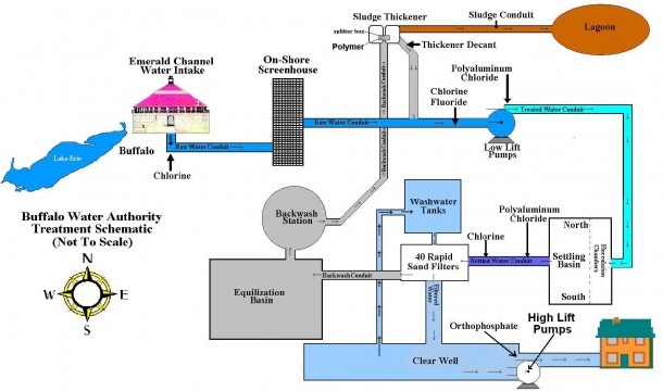
Water treatment plant diagram. Sewage treatment (or domestic wastewater treatment, municipal wastewater treatment) is a type of wastewater treatment which aims to remove contaminants from sewage to produce an effluent that is suitable for discharge to the surrounding environment or an intended reuse application, thereby preventing water pollution from raw sewage discharges. Sewage contains … Jul 26, 2014 · The Rapid Sand Filter (RSF) water treatment equipment differs from the Slow Sand Filter water treatment equipment in a variety of ways, the most important of which are the much greater filtration rate and the ability to clean automatically using back washing. The mechanism of particle removal also differs. Rapid sand Water filter does not use biological … Handbook of Water and Wastewater Treatment Plant Operations.pdf. 670 Pages. Handbook of Water and Wastewater Treatment Plant Operations.pdf. Muhammad Nasrullah. Download Download PDF. Full PDF Package Download Full PDF Package. This Paper. A short summary of this paper. 33 Full PDFs related to this paper. Water Treatment Plant (WTP) processes that are commonly used in getting clean potable water to your household. Civil Engineers design, monitor and maintain water treatment plants and water supplies. Civil engineers are vital in the treatment and delivery of water to your household. Water supply is the water that comes
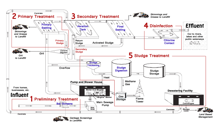
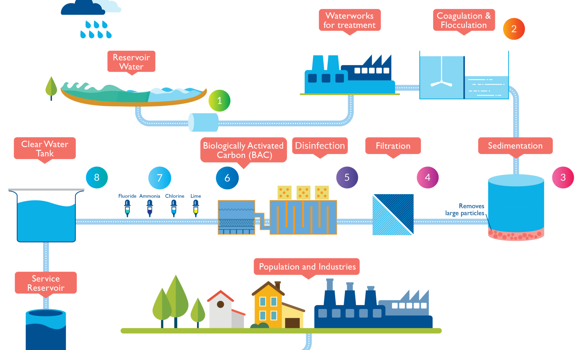
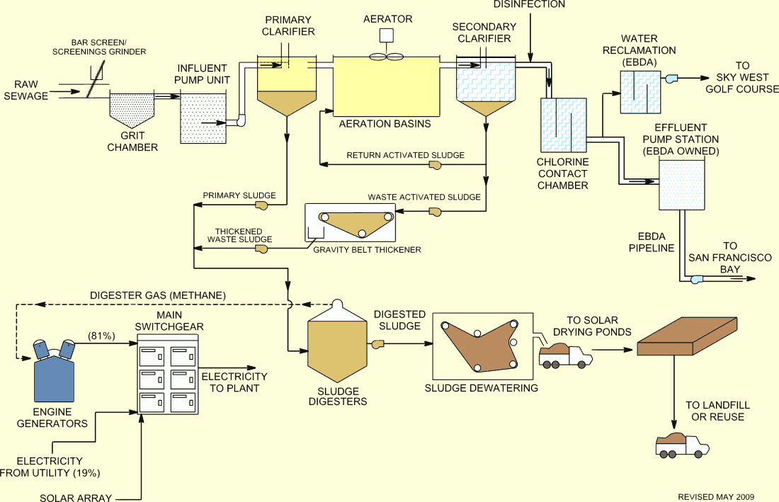
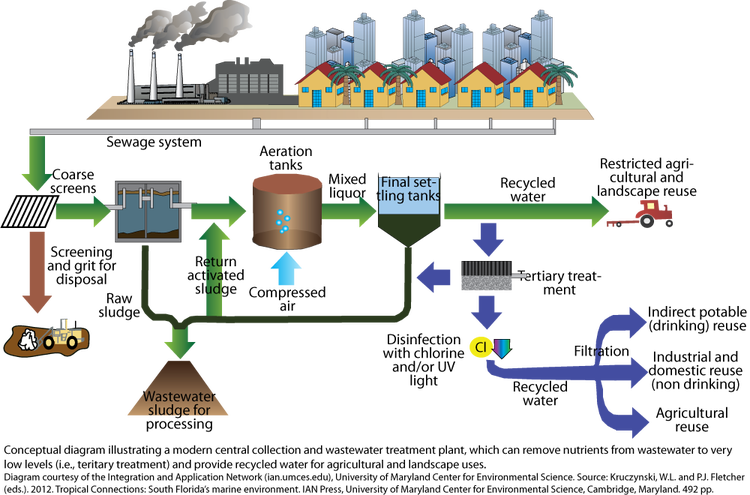
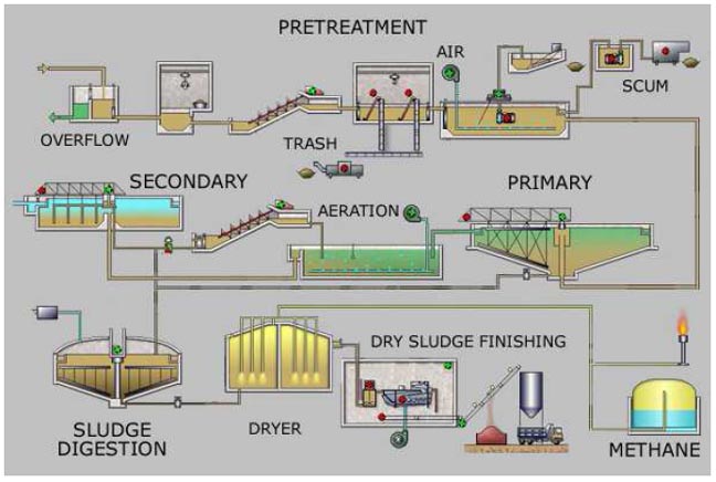
Dec 02, 2016 · Most municipal wastewater treatment facilities use primary and secondary levels of treatment, and some also use tertiary treatments. The type and order of treatment may vary from one treatment plant to another, but this diagram of the Ottawa-Carleton wastewater treatment plant illustrates the basic components. The wastewater treatment plant is designed to treat 250 gpm (56.8 m 3 h −1) of which 66% is recovered by the membrane processes and the rest through the brine evaporator/crystalliser unit (Fig. 5.6).The wastewater flow is generated by make-up RO reject (64%) (from make-up water plant), power block blowdown (22%) and mixed bed regenerate waste (14%). Water treatment plant. The primary purpose of a water treatment system is to bring raw water up to drinking water quality standards. The quality of the source water quality standards. Surface water will usually need to be filtered and disinfected. Groundwater, on the other hand, will often need to have hardness removed before disinfection ... Text in this Example: Drinking Water Treatment Sedimentation The heavy particles (floc) settle to the bottom and the clear water moves to filtration. Storage Water is placed in a closed tank or reservoir for disinfection to take place. The water then flows through pipes to homes and businesses in the community. Flocculation & Clarification Tank Lake, Reservoir or River Coagulation Filtration ...
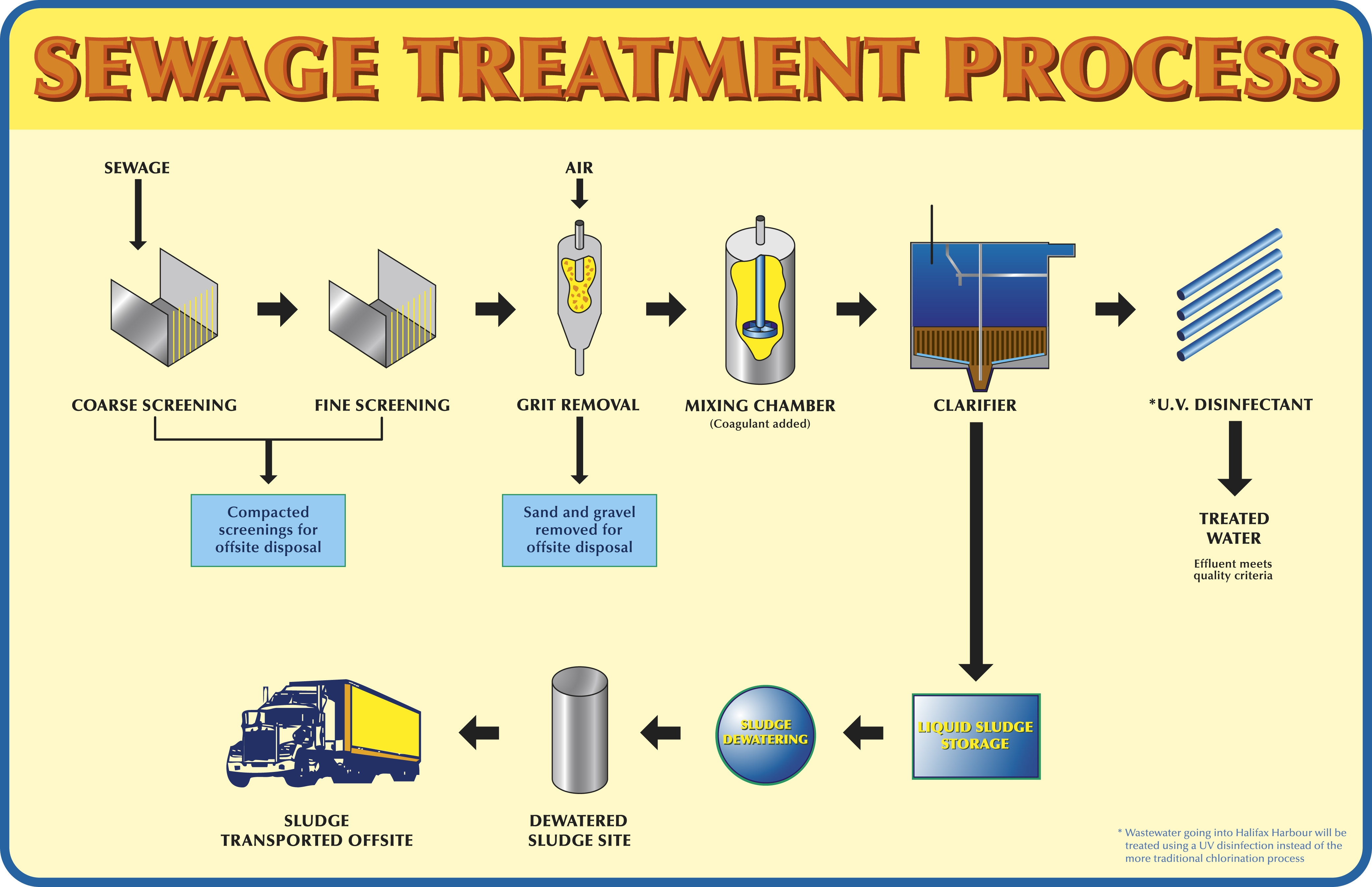
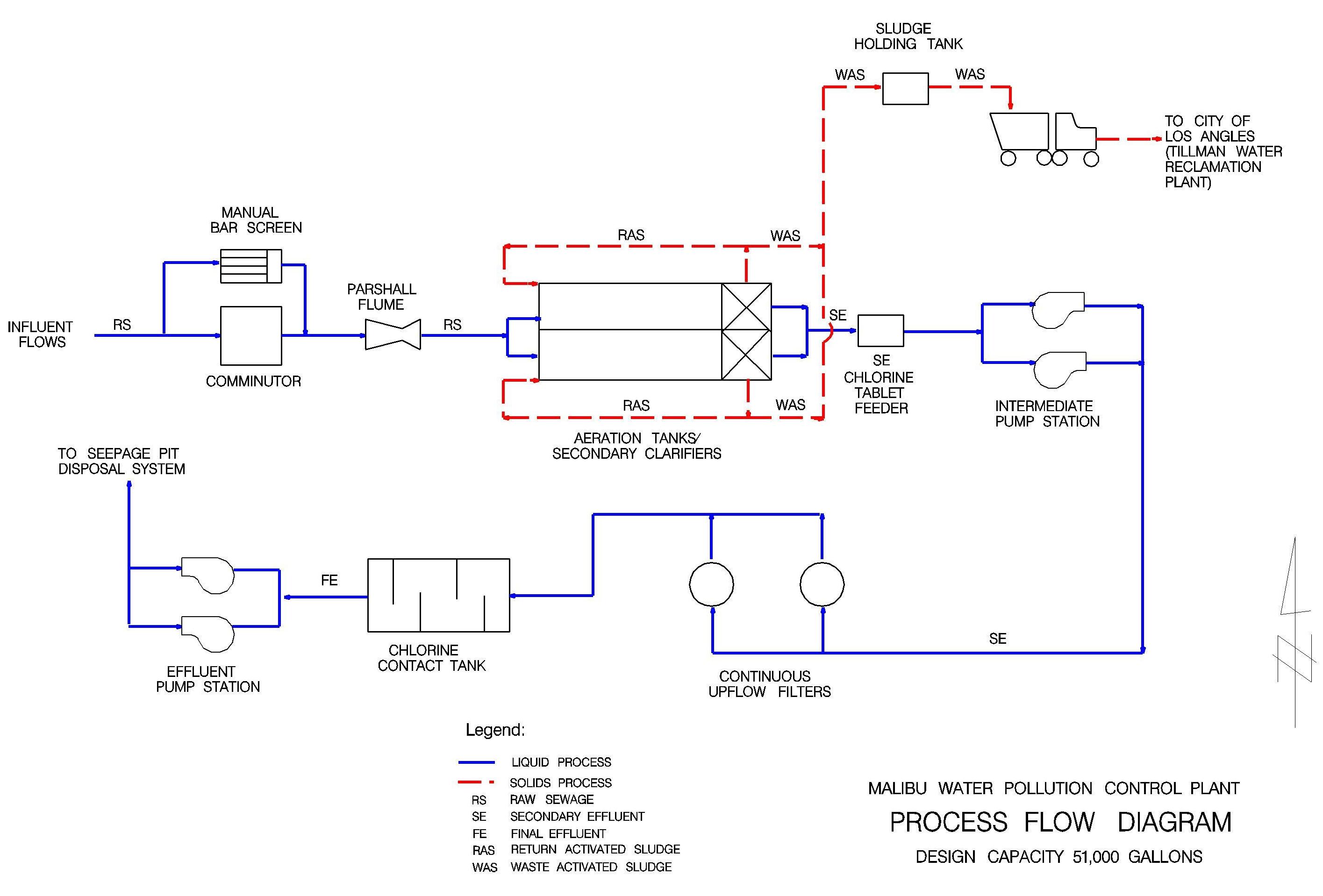
diagram of a typical treatment plant is developed as an example, data input options are outlined, and a general description of how to use the program is provided. • Chapter 4 provides guidance for interpretation of the output from the WTP program. The ORCA Sonar Bed Level System is one of our most popular products used throughout the water and wastewater industry. The ORCA Sonar Bed Level System will measure up to two density interfaces simultaneously. Typically these are bed levels / RAS blanket and floc / fluff layers. The sonar produces a high power concentrated beam, and provides ... The wastewater treatment plant is designed to treat 250 gpm (56.8 m 3 h −1) of which 66% is recovered by the membrane processes and the rest through the brine evaporator/crystalliser unit (Fig. 5.6).The wastewater flow is generated by make-up RO reject (64%) (from make-up water plant), power block blowdown (22%) and mixed bed regenerate waste (14%). Sewage/Waste Water Treatment —A Summary: A conventional sewage treatment plant has the requisite operating units arranged one after another for treatment and final disposal of sewage. The flow chart of a conventional sewage treatment plant is depicted in Fig. 57.18.
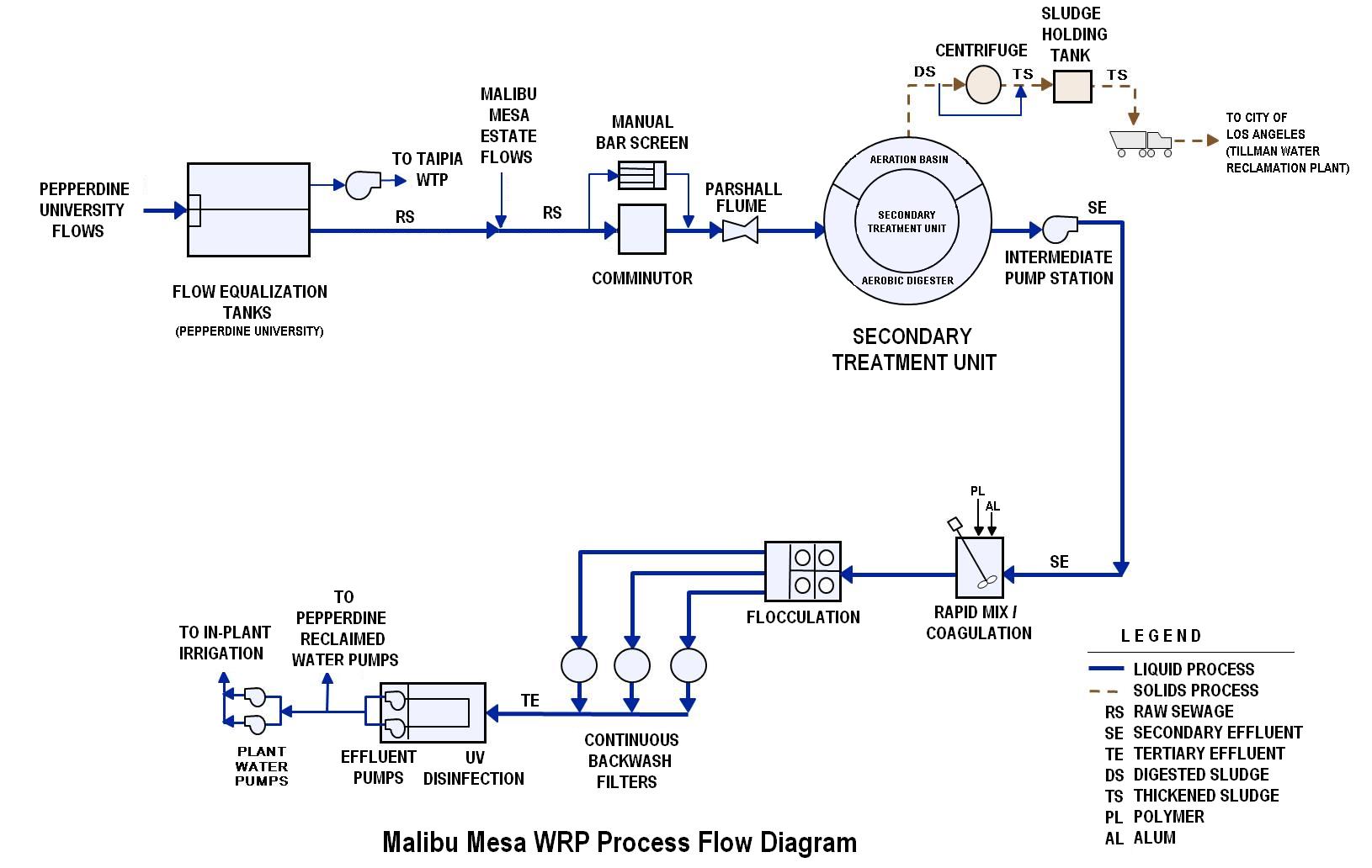
Drinking Water Treatment Plant Process Flow Diagram
The common steps of river water treatment are provided in Figure 3, and the processes are illustrated in the following diagram. 5 Citation: Shuokr Qarani Aziz et al. , 2019.

Illinois > Water Quality > Water Treatment
Fleming Training Center 2 Water Treatment Formulas Converting lbs/gal to mg/mL To use this diagram: First, find the box that coincides with the beginning units (i.e. mg/mL).

wastewater treatment plant diagram | architecture of the ...
Fig. 1: - Block diagram of waste water treatment plant. a) POWER SUPPLY UNIT: The power supply unit supplies the 24 v dc to both the plc processor and input output unit of the plc. b) PROCESS TANK: The waste water will fill in the process tank to remove
Wastewater Treatment Process | Wastewater Treatment ...

closeup photo of green leafed plant

wastewater treatment plant diagram | Infographics ...
30 Water Treatment Plant Process Flow Diagram - Free ...

Water Treatment Plant Diagram - General Wiring Diagram

green leaf plant
Water treatment plant process & Avlon Inc Product Line
Wastewater Treatment Operating Services Selection Guide ...
Waste Water Treatment Plant | MI Chesaning

Schematic depiction of water treatment plant. Courtesy of ...

Schematic diagram of the wastewater treatment plant ...
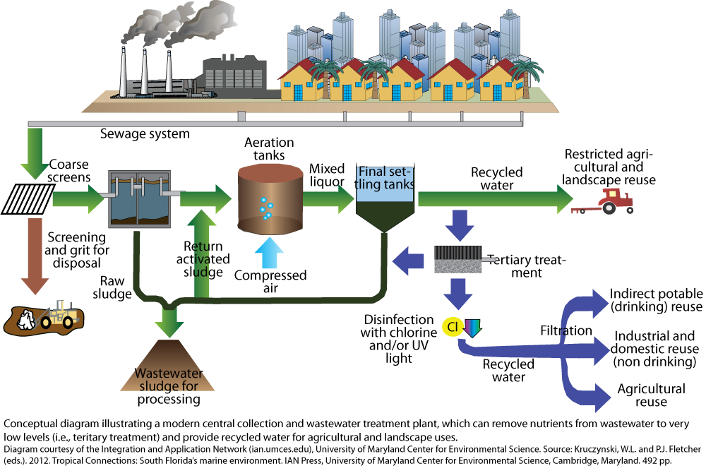
Modern Wastewater Treatment | Media Library | Integration ...
What happens in a water treatment plant? - Quora

Schematic illustration of a conventional wastewater ...

eYc FEM06 Electromagnetic Flowmeter industry application ...
Process of Wastewater Treatment Plant

Dirty to Clean: How a Water Treatment Plant Works
Effluent Usage in the Southwest - PureDrinkableWater
WWT Information | Halifax.ca

Water treatment plant. Diagram of the drinking water ...

green leafed plant

Wastewater Treatment Plant Schematic Diagram - Wiring ...
29 Wastewater Treatment Process Diagram - Wiring Diagram List
28 Sewage Treatment Plant Process Flow Diagram - Diagram ...
Treatment systems for intensive (Department of Environment ...

Conventional Water treatment process. | Download ...
Plant layout for the Central District Wastewater Treatment ...
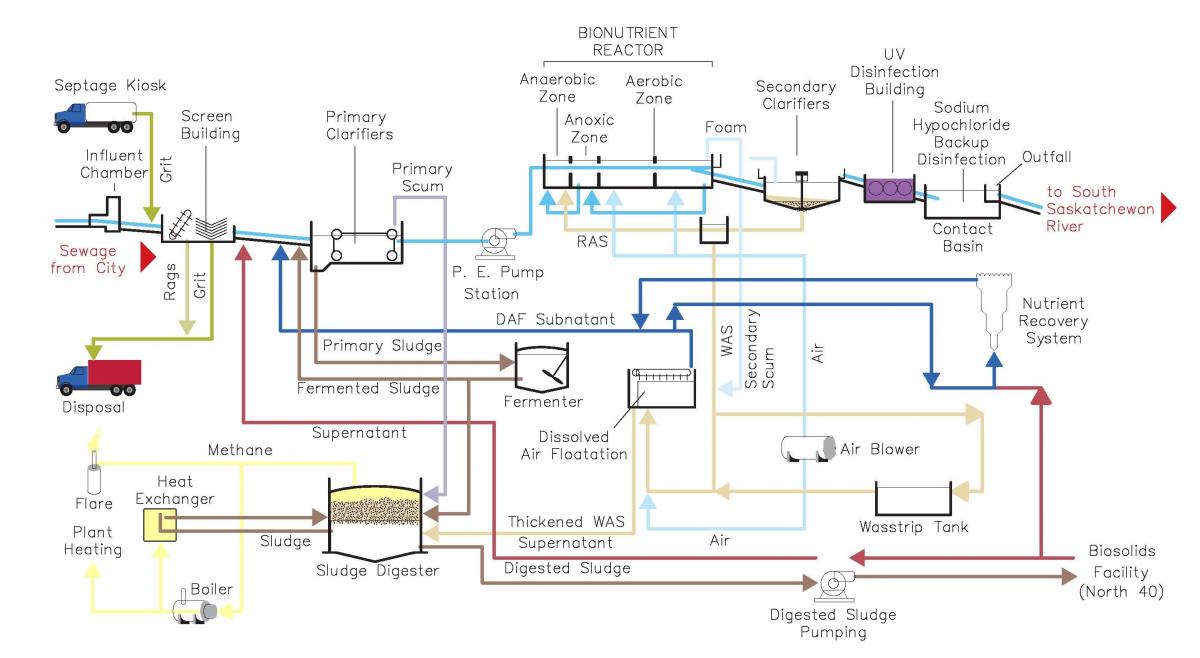
Wastewater Treatment Plant | Saskatoon.ca

-Diagram of a mechanical-biological wastewater treatment ...

palm trees

Flow diagram of the wastewater treatment plants under ...

Water Treatment | Dubuque, IA - Official Website
0 Response to "35 water treatment plant diagram"
Post a Comment