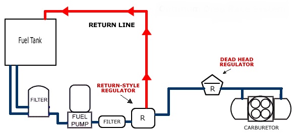
38 return style fuel system diagram
Another cause of failure is over-heated fuel. Not running a return line (dead-head style) or attempting to plumb the return line into the feed line (not into the tank) causes hot fuel to cycle back through the pump, heating it up more. The hotter the fuel, the easier it is to cavitate or even vapor lock. Yes, EFI systems can vapor lock too. Fuel Return to Tank 32. Priming Port 33. Quantity Control Valve 34. Rail Pressure Sensor 35. Water Drain 36. Check Ball 37. Low Pressure Sensor 38. Fuel Temperature Sensor 39. Pre-filter Drain 40. MCM Heat Exchanger 41. Throttle Valve 42. Valve Figure 2. Two-Filter Fuel System Overview (with MCM Heat Exchanger) 3 Fuel System (With MCM Heat ...
Step 1: Fill out pump finder above. Step 2: Add the pump to your cart. Step 3: Refer to the diagram on the product page for plumbing or refer back to this page and click the link to your fuel pump diagram. Step 4: Bulk add to cart! The following are the basic solutions to the most common systems. - For more specific variables please call tech at 913-647-7300

Return style fuel system diagram
Build Your Fuel System here! *Motion Raceworks Fox Body Giveaway. NO PURCHASE NECESSARY TO ENTER OR WIN.. Open to residents of the 48 contiguous United States and the District of Columbia (excluding AK, HI), who are age of majority & licensed drivers. The benefits of a dynamic, return-style fuel system are longer pump life, the elimination of unwanted pressure drops, a marked increase in pump-to-horsepower ratings, and quieter pump operation. There are some key benefits to a return-style setup. Vapor lock is mitigated because the constant cycle of fuel back into the tank cools the gasoline.; Engine tuning is easier because the fuel temperatures in a return-style system are typically more consistent.; Fuel pressure is more stable at the carburetor or injectors because you can place the regulator closer to the delivery point.
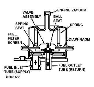
Return style fuel system diagram. Non-return style regulators are characterized by their lack of a fuel return line from the regulator back to the fuel tank. With a blocking style regulator, fuel enters through the inlet port (A), travels past the fuel control valve (B), and then is distributed through an outlet port to the carburetor. *HP estimates are based on gasoline. Individual systems will vary based on fuel system design, regulator type, fuel cell location, launch G’s etc. ** Return line only needed if using a By-Pass regulator such as the 12-803BP SN95 Return Style Fuel System Installation Diagram (Size: 379.8 KB) SN95 Return Style Fuel System Installation Diagram: M&H "The Tank" Installation Instructions (Size: 832 KB) Installation Instructions for 2005 & Newer Mustang Factory Disc Brakes on Moser Engineering #7705 housing ends (Size: 832 KB) So, with my recent mod fail and hair pulling trouble shooting, it’s important you learn from your mistakes. I’m going to go over the basics of a high-flow or...
There are some key benefits to a return-style setup. Vapor lock is mitigated because the constant cycle of fuel back into the tank cools the gasoline.; Engine tuning is easier because the fuel temperatures in a return-style system are typically more consistent.; Fuel pressure is more stable at the carburetor or injectors because you can place the regulator closer to the delivery point. The benefits of a dynamic, return-style fuel system are longer pump life, the elimination of unwanted pressure drops, a marked increase in pump-to-horsepower ratings, and quieter pump operation. Build Your Fuel System here! *Motion Raceworks Fox Body Giveaway. NO PURCHASE NECESSARY TO ENTER OR WIN.. Open to residents of the 48 contiguous United States and the District of Columbia (excluding AK, HI), who are age of majority & licensed drivers.

Aeromotive Fuel Pressure Regulator Diagram - Drivenheisenberg
"Easy" conversion from dead-head to return-type fuel ...

Fuel System Components - Fuelish Questions

what’s in my bag
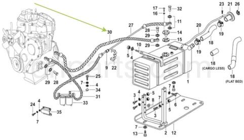
FUEL LINE RETURN: MAHINDRA 1001CA1050N -compatibility ...

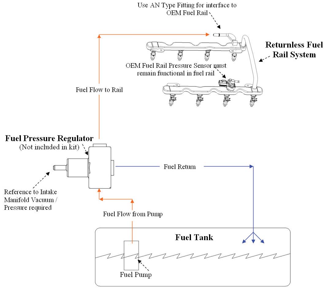
OEM Returnless Rail - Phantom 340 & Installation Kit ...

Fuel Cell Diagrams - Aeromotive, Inc

LSX foxbody fuel setup - LS1TECH
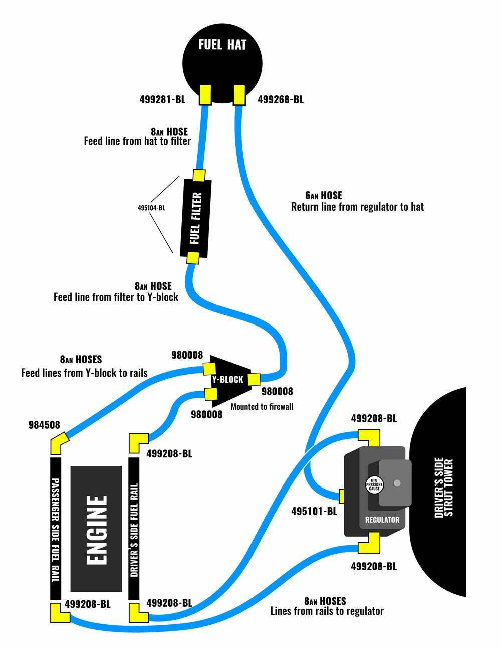
Lethal Performance Fuel System Series: Level 1 and 2 ...

Abandoned Architecture, Forteresse Medievale De Yevre-Le-Chatel Near Pithiviers, Central-Val De Loire, French Republic.

AEM AFPR return style routing - Miata Turbo Forum - Boost ...

India - Telangana - Hyderabad - Streetlife At Charminar Mosque - 24

For those of you that have installed efi, fuel pressure ...

Phantom Fuel System Diagrams - Aeromotive, Inc

Interesting read on returnless type fuel systems - K-Bikes ...

Readers Are Leaders

Selecting The Correct Regulator For Your Car - Holley Blog

Engine - Drivetrain - 1st Gen - Cooper - S - Return Style ...

Monochrome, Church Interior, Blois, Central-Val De Loire, French Republic.

India - Telangana - Hyderabad - Mecca Masjid - 27bb

1967 Mercury Cougar - Feeling Fuelish - Hot Rod Network
How to install a Ford Racing 4.6L 3V Crate Engine Control ...

Fuel System Components - Fuelish Questions

Architecture, Church Of Saint martin, Saran, Central-Val Et Loire, French Republic.

Getting dressed for interview

Get the Right Fuel System for Your Horsepower Needs ...

Water Reflection, The Falkirk Wheel, Falkirk, Stirlingshire, Scotland.
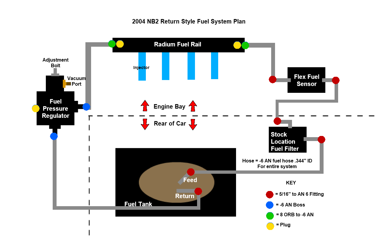
2004 NB2 VVT Fab9 BW EFR 6258 Build - Miata Turbo Forum ...

Tidy minimal interior

Strangers in Sync

Fuel System Components - Fuelish Questions
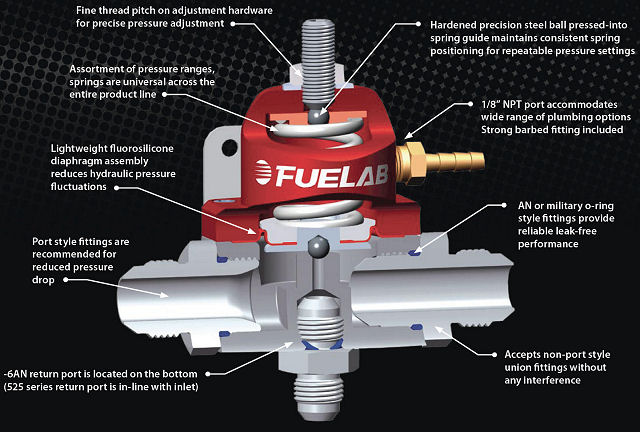
Aeromotive Fuel Pressure Regulator Diagram - General ...

India - Telangana - Hyderabad - Streetlife At Charminar Mosque - 19

Possible fuel starvation - Nissan Patrol GU/Y61 - myPatrol4x4

shivy: Fuel system
Aeromotive Stealth Fuel tank issues
Returnless Fuel System comparison Car Gas Flow Diagram

Edelbrock Return-Style Fuel System Kits
0 Response to "38 return style fuel system diagram"
Post a Comment