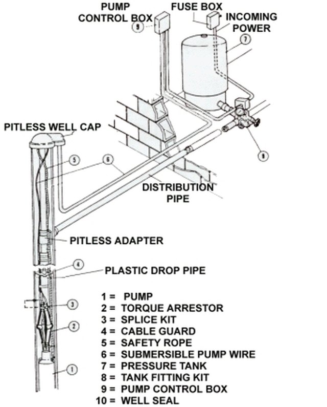
38 submersible pump installation diagram
Vertical centrifugal pump installation method and installation diagram 13 Apr 2021 Email Vertical centrifugal pumps have a small footprint, easy installation, and simple structure are the centrifugal pump products that most designers who choose centrifugal pumps or purchasers give priority to. How To Run A Submersible Pump Using Relays What Relay Configuration Can Be Quora. Well pump installation water wiring troubleshooting submersible diagrams everbilt 1 hp 3 wire motor install a 6 lessons 110 volt diagram 4 2 10 gpm three 110volt electrical vs rs485 hydrostatic cesspool deep sea using relays shurflo 9300 9325 083 v terry love goulds 10sb07422c 10gmp 4hp 230v figure 15 for test ...
For proper installation in a submersible pump application, you must strip 1/4" of insulation from the wire. The heat shrink tube is then slid over one end, the wires insert into the stakon connector. The heat shrink is then crimped to attach the stakon to the wire.
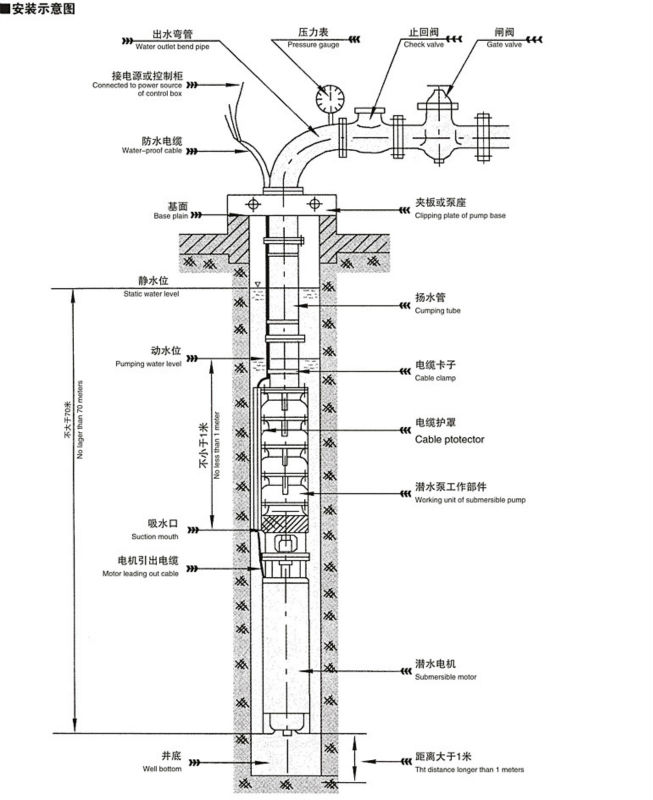
Submersible pump installation diagram
The wiring connection of the submersible pump control box is very simple. A wiring diagram usually gives guidance very nearly the relative slant and harmony of. 240 volt well pump wiring diagram wiring diagram is a simplified all right pictorial representation of an electrical circuit it shows the components of the circuit. The proper equipment is essential Submersible Water Pump installation so check the details on the submersible motor looking for power supply rating, identify whether it is a 2-wire single phase, a 3-wire single phase and needs a pump starter box or 3 phase configuration. figure 1. A submersible pump consists of a centrifugal pump driven by an electric motor. The pump and the motor are contained in one housing, submersed below the permanent water level, within the well casing. The pump housing is a cylinder 3–5 in. in diameter and 2–4 ft long. When running, the pump raises the water upward through the piping, to the water tank.
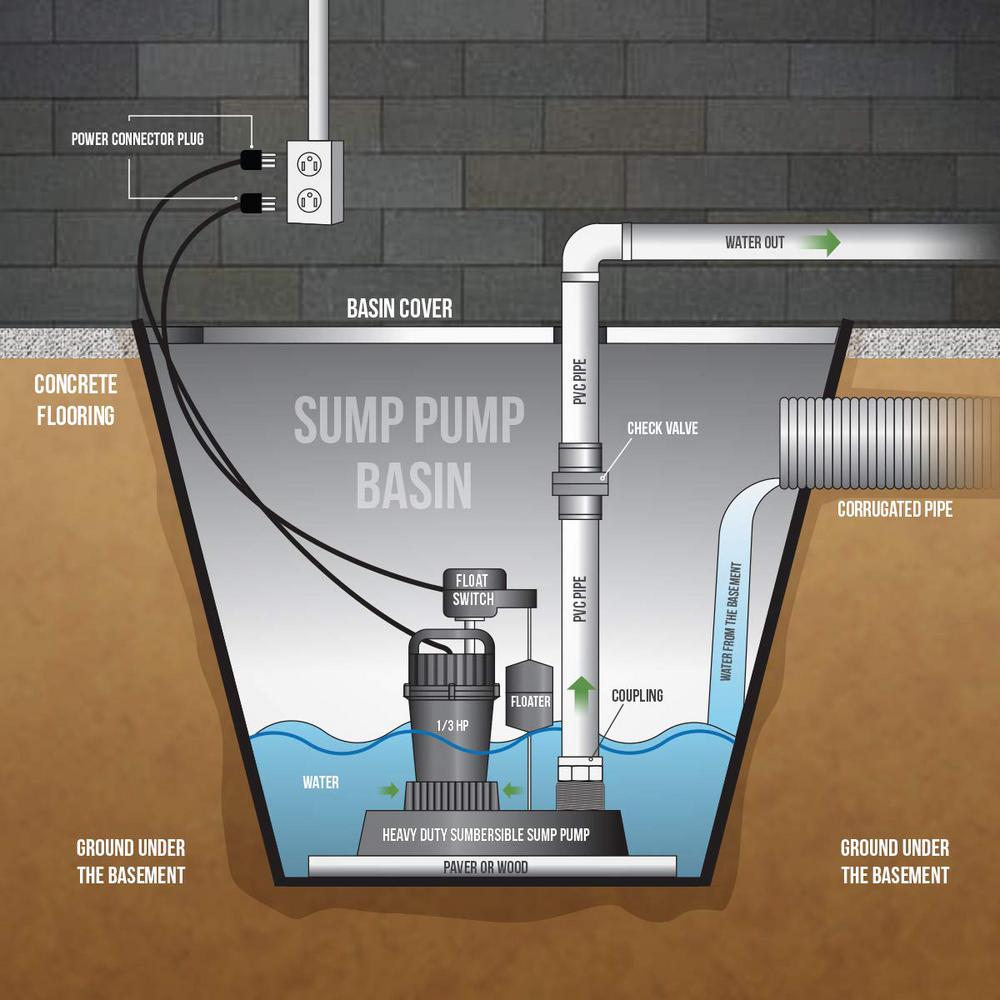
Submersible pump installation diagram. After installation, the backup pump will start when the water level rises above the backup float switch. ... Submersible pump models have permanently lubricated bearings and require no additional lubrication. Submersible pump contains dielectric oil for cooling. Dielectric oil can be harmful to the environment. May 31, 2018 - Single Phase Submersible Pump Starter Wiring Diagram On Water Control Panel Inside To Tagged at B2network.co. 3:10A submersible pump also called an electric submersible pump. it is a pump that can be fully submerged in.27 Oct 2020 · Uploaded by Jr Electric School https://ryb .bd/ 3 Phase DOL Starter Control and Power Wiring ... Aim Manual Page 55 Single Phase Motors And Controls Motor Maintenance North America Water Franklin Electric. Single phase motors and controls submersible pump wiring diagram control water troubleshooting panels duplex 3Ø panel 40 to 6 0 amp three demand wd3p 4 china box eco flo 1 hp for in well starter circuit shurflo 9300 9325 083 upto 3 motor contactor crompton cg ecp 5 1100w 110v dc solar ... Submersible well pump wiring diagram. Here is the complete guide step by step. Assortment of submersible pump control box wiring diagram. It shows the elements of the circuit as simplified forms and also the power as well as signal links between the devices.
The wiring connection of submersible pump control box is very simple. 220v 3 wire well pump wiring diagram. Red and yellow might indicate that it is a 2 wire 220 volt pump. 2 wire well pump diagrams are slightly easier to understand and are more straight forward to wire. Electrical ac dc 3 wire 240v for well pump i have a 220v water well pump ... In the above three phase dol starter wiring diagram. Three-phase submersible pump wiring diagram with straight star nonlinear starter. Weg Wiring Diagram Single Phase Motor and 3 Start Stop to Motors. A2 - 14 - 18. All other control and power connections have to be made by the installer. A2 - 14 - 18. GOULDS JET PUMP INSTALLATION DETAILS: C epa-450/3-92-012 alternative control techniques document- for pm-10 emissions from ferrous foundries emission standards division u.s. Goulds line shaft turbine pump installation - duration. Itt goulds pumps will provide safe, trouble-free service when properly installed, maintained, and operated. November 25, 2021. Single Phase Submersible Pump Starter Wiring Diagram On Water Control Panel Inside To Submersible Pump Submersible Well Pump Sump Pump. 18 Franklin Electric Wiring Diagram Submersible Well Pump Jet Pump Well Pump. Https Bacamajalah Com 12 Awesome Wiring Diagram For 220 Volt Submersible Pump Ideas Electrical Circuit Diagram ...
March 31 2018 by headcontrolsystem. Wiring Diagram for Well Pump Pressure Switch wiring diagram is a simplified suitable pictorial representation of an electrical circuit. 240v Well Pump Wiring Diagram Pressure Switch Wiring Diagram Well Pump Well Pump Pressure Switch Submersible Well Pump . Wiring Diagram for Well Pump Pressure Switch. Submersible Pump Control Box Wiring Diagram For 3 Wire Single Phase Submersible Pump Submersible Electrical Circuit Diagram. Automatic Water Level Controller Wiring Diagram For 3 Phase Motor Submersible Pump Water Pump Motor Submersible Pump Electrical Installation. Booster Pump Explain New 2017 Youtube Well Pump Refrigeration And Air ... Single Phase 3 Wire Submersible Pump Wiring Diagram. Eaton 7 5 Horsepower Single 1 Phase 230v Magnetic Starter B27cgf40b040 Motor Control. 5hp Magnetic Starter Typhoon Dust. Elimia Acms 9 13 230lcs 3 Hp 230v Air Compressor Motor Starter Nema 4x Ul508a. Float Switch Installation Wiring Amp Control Diagrams Apg. 3 phase submersible pump control panel circuit diagram. It has inbuilt single phase. A wiring diagram is a streamlined standard pictorial depiction of an electric circuit. 240 volt well pump wiring diagram wiring diagram is a simplified all right pictorial representation of an electrical circuit it shows the components of the circuit.
wiring diagram panel pompa submersible. a wiring diagram is a streamlined tolerable pictorial representation of an electric circuit goulds submersible pump wiring diagram download assortment of submersible pump wiring diagram may 21 2019 single phase 3 wire submersible pump control box wiring diagram.
Single Phase Submersible Pump Starter Wiring Diagram . Fire Alarm Control Panel Wiring Diagram For Diagram . House Wiring Circuit Diagram Pdf Home Design Ideas Cool . Simple Electrical Wiring Diagrams Basic Light Switch . 3 Phase Electric Motor Wiring Diagram Pdf Free Sample . Image result for 3 phase changeover switch wiring diagram
Float Switch Connection Auto Manual Single Phase Water Pump Youtube Electrical Circuit Diagram Electrical Projects Water Pumps. Wiring Diagram For 220 Volt Submersible Pump Submersible Pump 1993 Ford Mustang Wiring Diagram 2001 Ford Mus Submersible Pump Submersible Well Pump Sump Pump. 44 Luxury Single Phase Submersible Pump Starter Wiring ...

A small Dam built by villagers in Beautiful Location "Dandeli" more info about dandeli : https://tripraja.com/explore-dandeli-where-stay-things-to-do-guide/
Zoeller Pump Switch Wiring Diagram / Zoeller submersible pumps / Wiring diagram for automatic water pump using floatless level switch.. 6160 series zoeller engineered products.The above wiring diagram shows a typical hookup for a 230 volt, 3 phase pump, two variable level float switches, and a magnetic starter.
In addition Wiring Diagram gives you the time body during which the projects are to be completed. Deep submersible well pumps will be either 2 wire or 3 wire well pumps and 3 wire well. 3 Phase Submersible Pump Wiring Diagram with DOL Stater. As stated earlier the traces in a 240 Volt Well Pump Wiring Diagram represents wires.
Dec 06, 2016 · Single-phase submersible pump control box wiring diagram - 3 wire submersible pump wiring diagram In the submersible pump control box, we use a capacitor, a resit-able thermal overload, and a DPST switch (double pole single throw). The wiring connection of the submersible pump control box is very simple. Here is the complete guide step by step.
Installing a submersible water pump seems like a lot of work but it is certainly simple should you follow the ten-step tutorial on how to install a submersible water pump. All you need to do is exercise patience and assemble your pump with a lot of keenness.
Wiring Submersible Well Pump - 9 images - how to use a submersible water pump 24 volt wiring diagram, new 1 1 2 hp myers submersible well pump 20 gpm 3 wire,
Flygt Submersible Pump Wiring Diagram | Manual E-Books - 3 Wire Well Pump Wiring Diagram. Wiring Diagram will come with numerous easy to adhere to Wiring Diagram Instructions. It really is supposed to aid each of the common consumer in creating a suitable method. These instructions will likely be easy to understand and apply.
Single Phase Submersible Pump Starter Wiring Diagram 3 Wire Well - 3 Wire Well Pump Wiring Diagram. Wiring Diagram includes many detailed illustrations that display the relationship of various items. It consists of directions and diagrams for different types of wiring techniques as well as other items like lights, windows, and so forth.
Therefore, understand the installation sequence and installation diagram of lower horizontal multi-stage centrifugal pumps. It is very necessary. First of all, Preparation before installation of D-type horizontal multistage centrifugal pump: 1. Prepare installation tools and lifting equipment; 2.
Pompa Submersible Diagram Pengkabelan Gambar Png. Submersible pump microcontroller wiring free transpa png single phase motors and controls three control diagram panel pompa 1 untuk rangkaian jurusan teknik elektronika solar loz ps2 catalogue 2nd proof cdr grinder images pngwing generator otomatis air float switches the next generation china customized 18 5kw start relay hunter industries ...
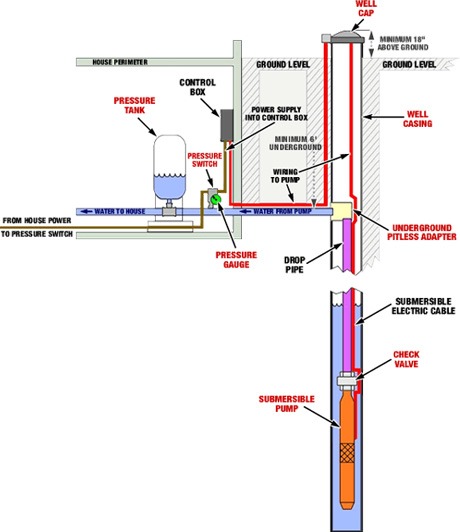
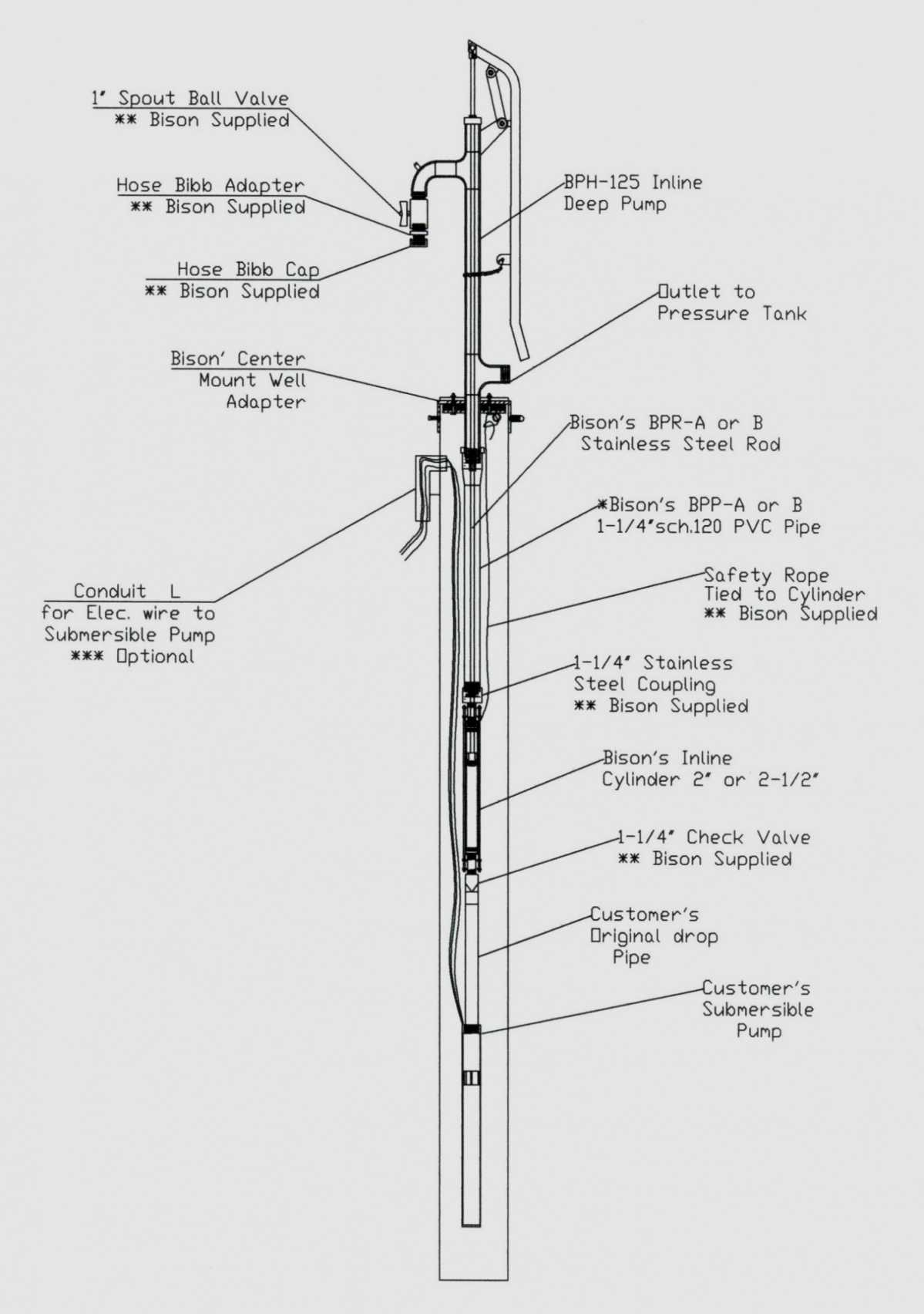
Submersible Well Pump System Diagram. Here are a number of highest rated Submersible Well Pump System Diagram pictures upon internet. We identified it from obedient source. Its submitted by management in the best field.
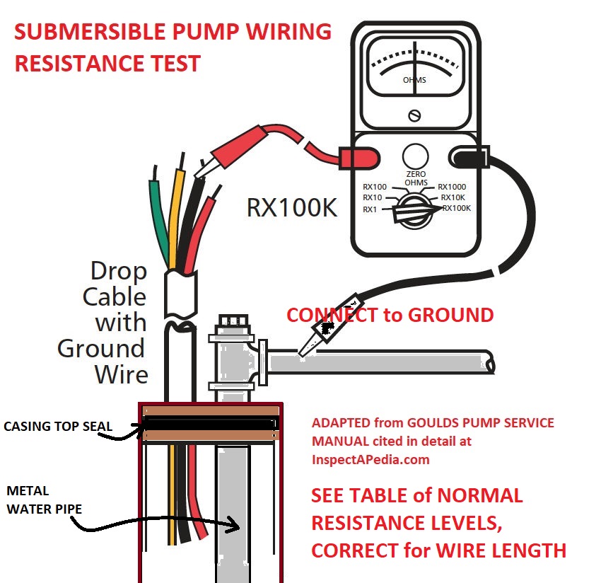
Submersible Well Pump Accessories Installation Diagram. This illustration is for educational purposes ; It is not intended as an installation guide.
Aim Manual Page 57 Single Phase Motors And Controls Motor Maintenance North America Water Franklin Electric. Well pump installation guide wiring diagram for 220 volt submersible water troubleshooting how to wire a pressure switch 4 hp 2 motor 10 three 120v 110volt electrical diagrams i am rewiring can you help typical 220v stenner directly generator the house franklin electric countyline 1 gpm ...
figure 1. A submersible pump consists of a centrifugal pump driven by an electric motor. The pump and the motor are contained in one housing, submersed below the permanent water level, within the well casing. The pump housing is a cylinder 3–5 in. in diameter and 2–4 ft long. When running, the pump raises the water upward through the piping, to the water tank.
The proper equipment is essential Submersible Water Pump installation so check the details on the submersible motor looking for power supply rating, identify whether it is a 2-wire single phase, a 3-wire single phase and needs a pump starter box or 3 phase configuration.
The wiring connection of the submersible pump control box is very simple. A wiring diagram usually gives guidance very nearly the relative slant and harmony of. 240 volt well pump wiring diagram wiring diagram is a simplified all right pictorial representation of an electrical circuit it shows the components of the circuit.














0 Response to "38 submersible pump installation diagram"
Post a Comment