35 in a data flow diagram external entities are represented by
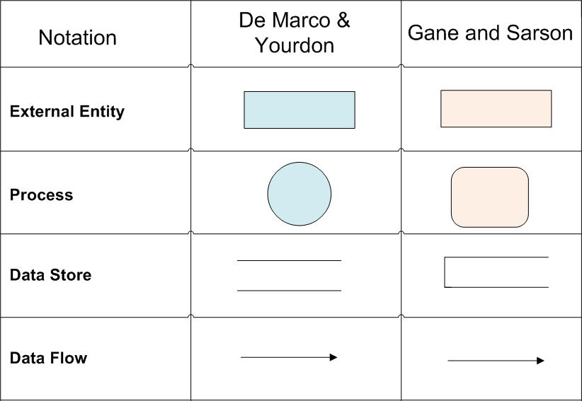
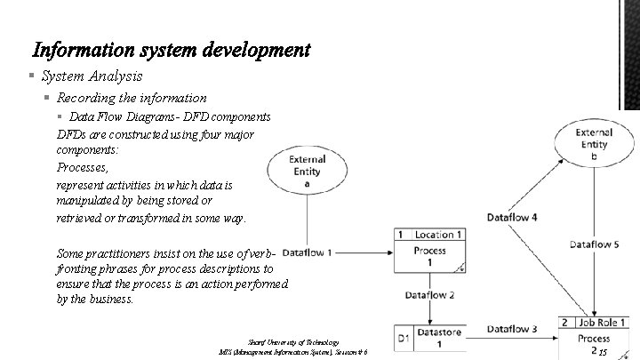
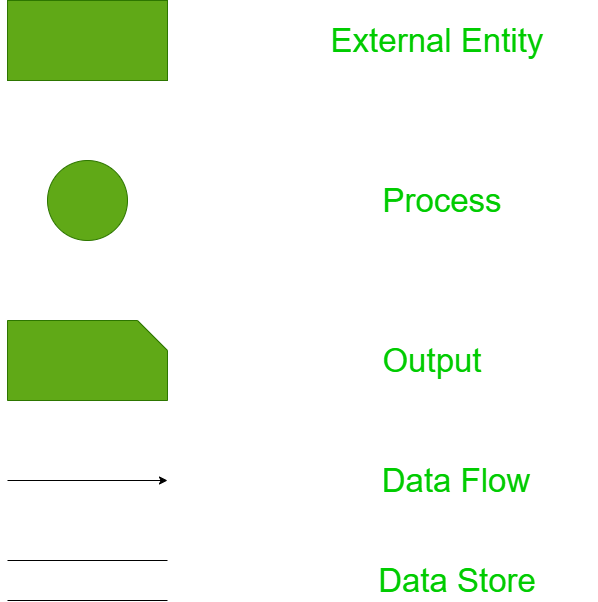
5.1.1 In a DFD external entities are represented by a (a) rectangle (b) ellipse (c) diamond shaped box (d) circle 5.1.2 A data flow can (a) only emanate from an external entity (b) only terminate in an external entity (c) may emanate and terminate in an external entity (d) may either emanate or terminate in an external entity but not both Data Flow Diagrams are composed of the four basic symbols shown below. The External Entity symbol represents sources of data to the system or destinations of data from the system. The Data Flow symbol represents movement of data. The Data Store symbol represents data that is not moving (delayed data at rest).
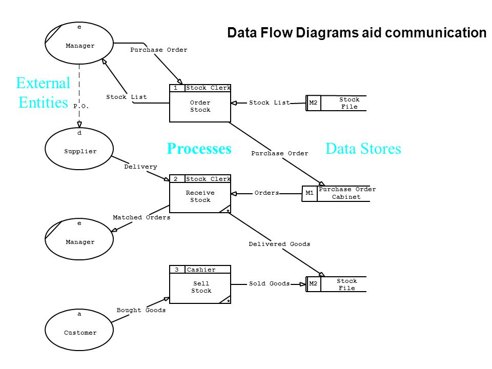
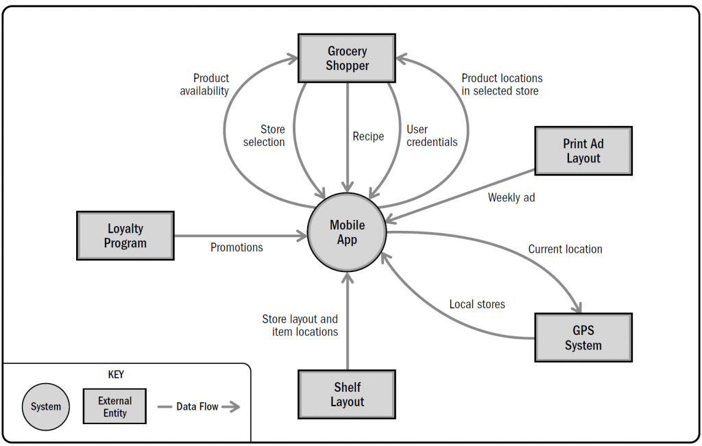
External entities are represented on the diagram as ovals drawn outside of the system boundary, containing the entity name and an identifier. Figure 6.5. Notation for external entities Names consist of a singular noun describing the role of the entity. Above the label, a lower case letter is used as the identifier for reference purposes.
In a data flow diagram external entities are represented by
The flow from the warehouse usually ... and the flow to the warehouse usually expresses data entry or updating (sometimes also deleting data). Warehouse is represented by two parallel lines between which the memory name is located (it can be modeled as a UML buffer node). ... The Terminator is an external entity that communicates ... External Entity – Also known ... diagrammed. These data flows are the inputs and outputs of the DFD. Since they are external to the system being analyzed, these entities are typically placed at the boundaries of the diagram. They can represent another system or indicate ... Q.4 In a DFD external entities are represented by a A) Rectangle B) Ellipse C) Diamond-shaped box D) Circle. ... Q.8 A data flow can A) Only emanate from an external entity B) Only terminate in an external entity C) May emanate and terminate in an external entity
In a data flow diagram external entities are represented by. May 15, 2021 - All use the same labels and similar shapes to represent the four main elements of a DFD — external entity, process, data store, and data flow. ... An external entity, which are also known as terminators, sources, sinks, or actors, are an outside system or process that sends or receives data to and from the diagrammed ... Data-flow diagrams (DFDs) model a perspective of the system that is most readily understood by users ... • data stores • external entities ... A process is represented in the model only where the information which provides the input into the Data Flow Diagram A Data Flow Diagram (DFD) is a graphical representation of the "flow" of data through an information system (as shown on the DFD flow chart Figure 5 ), modeling its process aspects. Often it is a preliminary step used to create an overview of the system that can later be elaborated. An external entity can represent a human, system or subsystem. It is where certain data comes from or goes to. It is external to the system we study, in terms of the business process. For this reason, people used to draw external entities on the edge of a diagram. Process
Start studying ISA 387 Ch 5. Learn vocabulary, terms, and more with flashcards, games, and other study tools. 5.1.1 In a DFD external entities are represented by a (a) rectangle (b) ellipse (c) diamond shaped box (d) circle 5.1.2 A data flow can (a) only emanate from an external entity (b) only terminate in an external entity (c) may emanate and terminate in an external entity (d) may either emanate or terminate in an external entity but not both There are four basic symbols to represent a data flow diagram. 1. External entity. External entities are objects outside the system with which system communicates. These are sources and destinations of the system inputs and outputs. They are also known as terminators, sinks, sources or actors. External Entity. Data flow is the lines with arrows that are used to mark where the data flows. As external entities create processes and interact with data stores, data flow lines map out these inputs and outputs. Data flow lines are an essential aspect of a data flow diagram as they tie all of the information together.
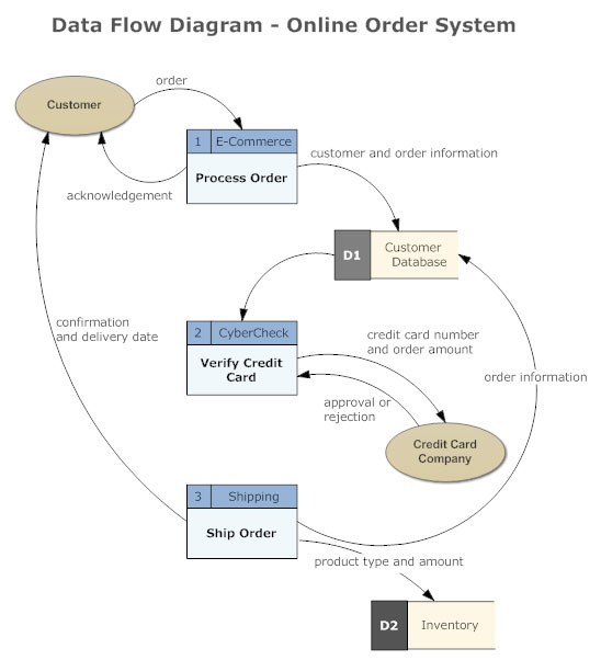
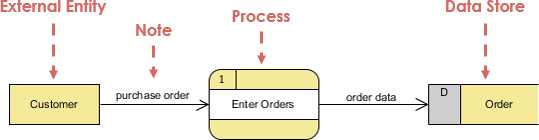
A data-flow diagram of the scope of an organizational system that shows the system boundaries, external entities that interact with the system, and the major information flows between the entities and the system. balancing The conservation of inputs and outputs to a DFD process when that process is decomposed to a lower level DFD completeness External entities are components outside of the boundaries of the information systems. They represent how the information system interacts with the outside world. A rectangle represents an external entity They either supply data or receive data They do not process data Notation A customer submitting an order and then receive a bill from the system In a data flow diagram, external entities are represented by: rounded boxes. square boxes. circles. open rectangles. triangles. square boxes. THIS SET IS OFTEN IN FOLDERS WITH... Therefore, add an External Entity to diagram and name it Customer. Like creating process, you can create an external entity by dragging External Entity from diagram toolbar to diagram. A data flow is used to represent the movement of data between different parts of the system. In this case, "order" is a data created by customer and ...
Data Flow Diagram - Everything You Need to Know About DFD
A data flow diagram (DFD) does not show the external entities that provide data to the system or receive output from the system. records In a data dictionary, data elements are combined into _____ that are meaningful combinations of data elements that are included in data flows or retained in data stores.
Data Flow Diagram (DFD) Symbols - EdrawMax
Data Flow Diagram visualizes processes, data depositories, and external entities in information systems and data flow connecting these elements. Data Flow Diagram consists of the following components: Processes and functions which represent actions that happened in the information system;
Chapter 8 : Structuring System Requirements (Process ...
1 In a DFD external entities are represented by a a Rectangle b Ellipse c from CSEG 265 at University of Petroleum and Energy Studies.

Components of Data Flow Diagrams | Toolbox Tech
External entities are represented by squares as the source or destination of data. Processes are represented by rectangles with rounded corners. Data Flows are referred to by arrows to denote the physical or electronic flow of data. Data Stores are physical or electronic-like XML files denoted by open-ended rectangles.
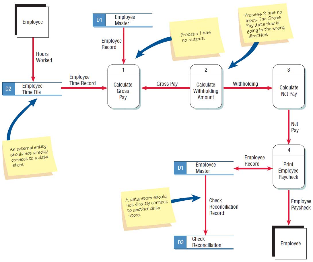
Checking the Data Flow Diagrams for Errors
In the data flow diagram, external entities (input/output) are represented by which of the following shape? of A). Diamond B). Triangle C). Circle D). Rectangle ...
FORMALIZATION OF THE DATA FLOW DIAGRAM RULES FOR CONSISTENCY ...
A data flow diagram (DFD) maps out the flow of information for any process or system. It uses defined symbols like rectangles, circles and arrows, plus short text labels, to show data inputs, outputs, storage points and the routes between each destination. Data flowcharts can range from simple, even hand-drawn process overviews, to in-depth ...

Comparison of Diagramming Tools
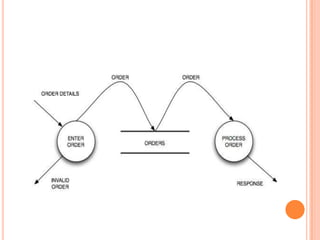
Data flows cannot run between two external entities without going through a process (as you will see in the data flow diagram examples below). Advantages and disadvantages of data flow diagrams: Before going further to data flow diagram examples, let's see what are some key benefits and cons of DFD.
What is Data Flow Diagram? Symbols and Example -
In a DFD external entities are represented by a Rectangle Ellipse Diamond shaped box Circle. Systems Analysis and Design Methods Objective type Questions and Answers. A directory of Objective Type Questions covering all the Computer Science subjects.
Data Flow Modelling Concepts  Data Flow Diagrams ...
Start studying ISA 387 Chapter 5 Quiz. Learn vocabulary, terms, and more with flashcards, games, and other study tools.
Data Flow Diagram Symbols, Types, and Tips | Lucidchart
A DFD is a flow chart that represent how data flows in a system A DFD is is a way to structure an organization using different levels of authority and a vertical link, or chain of command, between superior and subordinate levels of the organization A DFD is a chart showing how data is handled

Software Engineering Data Flow Diagrams - javatpoint
October 25, 2019 - Once you’ve identified the major ... context diagram is simple. Draw a single process node and connect it to related external entities. This node represents the most general process information undergoes to go from input to output. The example below shows how information flows between various ...
Data Flow Diagrams
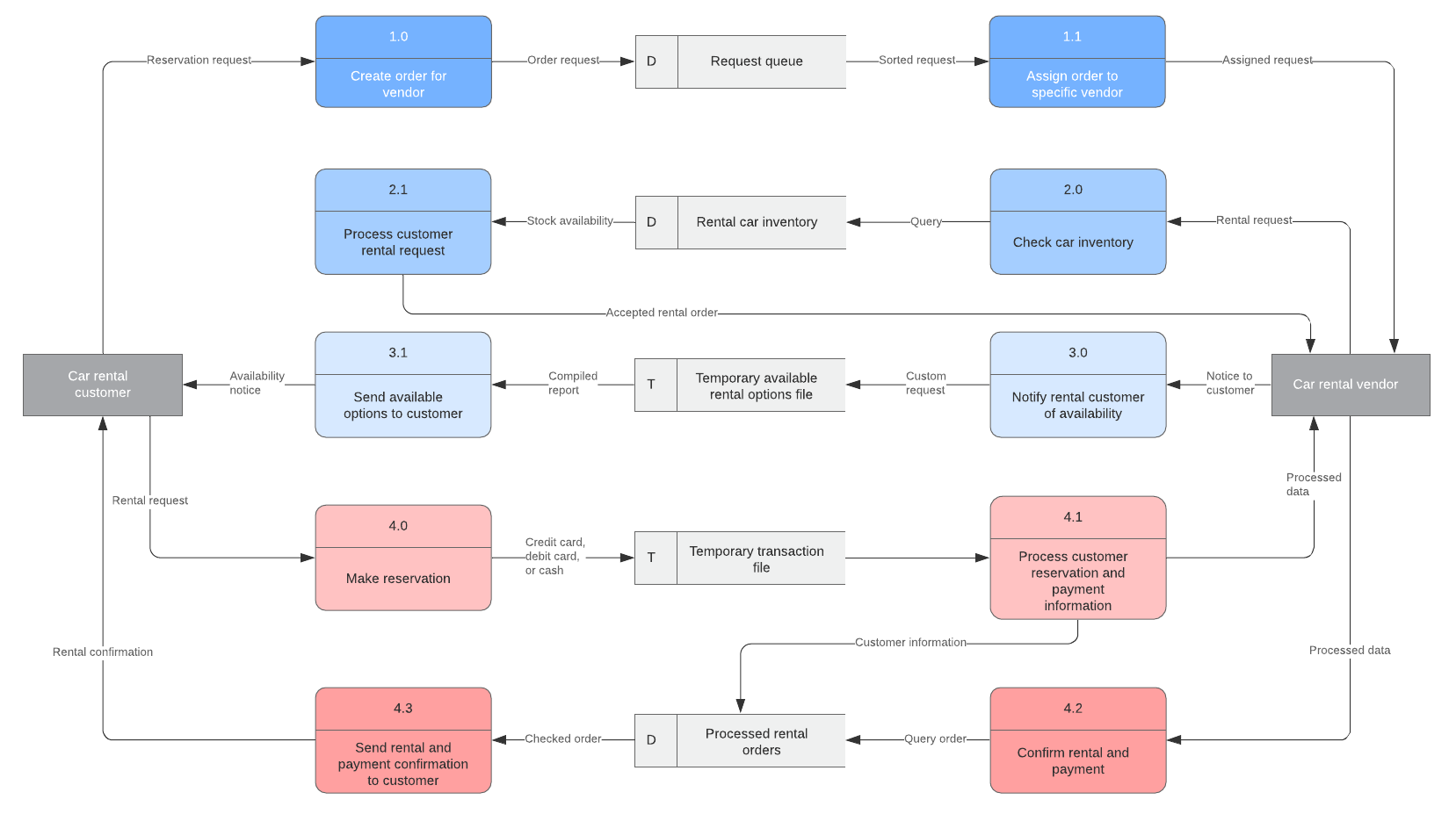
Here, we will see mainly 3 levels in the data flow diagram, which are: 0-level DFD, 1-level DFD, and 2-level DFD. It is also known as a context diagram. It's designed to be an abstraction view, showing the system as a single process with its relationship to external entities. It represents the entire system as a single bubble with input and ...

Comparison of Diagramming Tools
Start studying chap 5. Learn vocabulary, terms, and more with flashcards, games, and other study tools.

Comparison of Diagramming Tools
Carlos has a Level 0 DFD diagram where one of the external entities is the "Internal Revenue Service" - and he has a data store called "Tax Rate Table". He has drawn a data flow arrow from the Internal Revenue Service to the data store as the data has been loaded into the Tax Rate Table prior to the processing.

Data Flow Diagram | Examples, Symbols and Levels
Data flow diagram is a form of process modelling that helps in showing the movement of data between external entities, process and data stores within a system. It is a structural analysis technique which is used to increase software development productivity.
Sharif University of Technology Session 6 Contents Systems
Learn about data flow diagrams, including how they are used and how to create a DFD. Discover the difference between logical and physical DFDs.

Food Ordering System DFD (Data Flow Diagrams) | Itsourcecode.com
By leveling a DFD, we mean. splitting it into different levels. summarizing a DFD to specify only the essentials. expanding a process into one or more sub-processes giving more detail. make it structure uniform. 9. The following DFD is NOT correct as. there is no external entity. there is no output data flow from the process.
What is Data Flow Diagram?
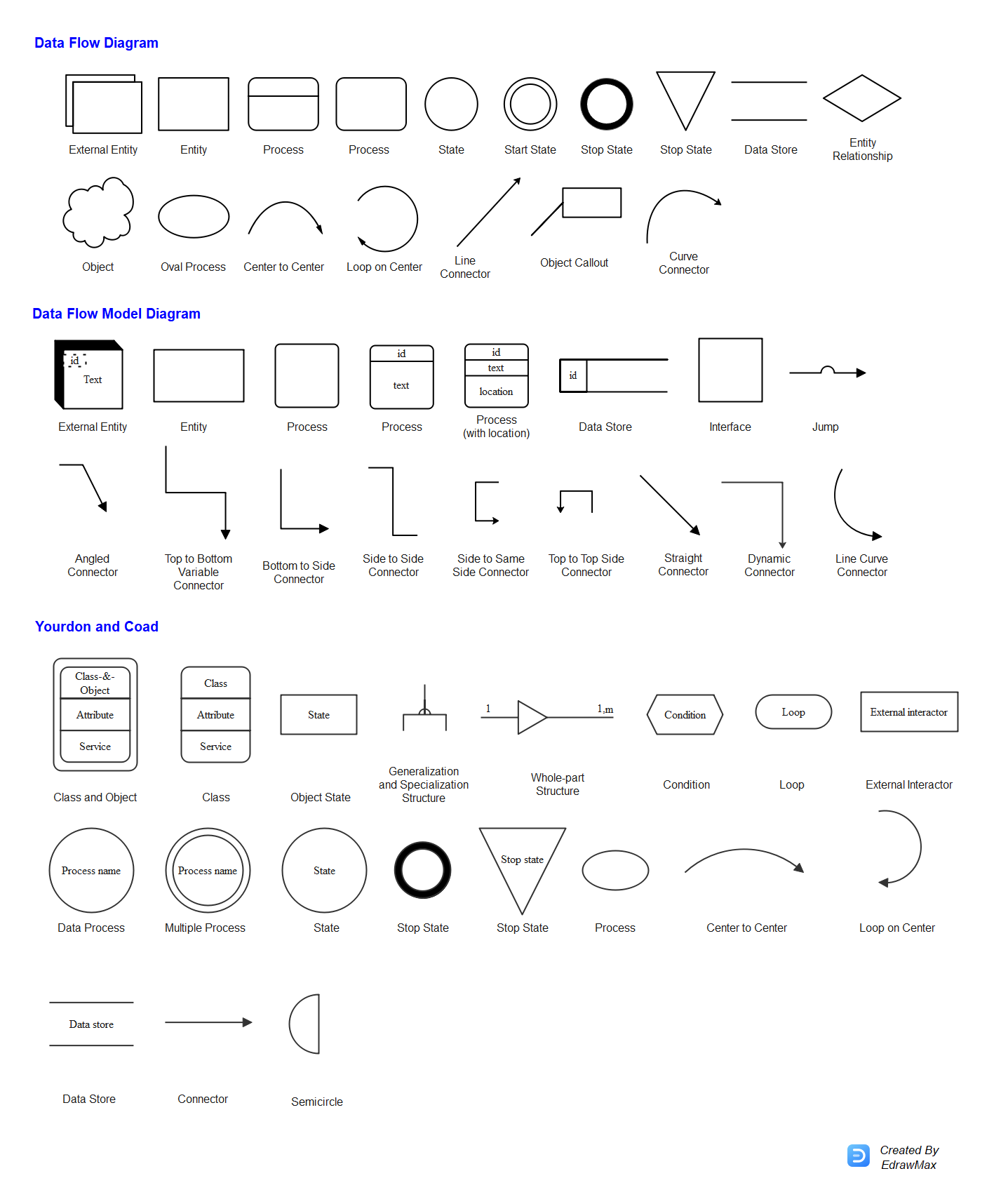
Data Flow Model Symbols. Pre-drawn data flow model symbols represent external entity, process w/location, data store, interface, jump, etc. These symbols help create accurate diagrams and documentation. Edraw software provides you many data flow model diagrams, external entity, process w/location, data store, interface, jump, angled connector ...
What is a data flow diagram? - Quora
What is an Data Flow Diagram (DFD)? Learn about data flow diagram symbols and DFD levels and types. Read the data flow diagram tutorial. See DFD examples.
Data Flow Diagram Online | DFD Maker | Tips and Templates ...
Data Flow Diagrams are composed of the four basic symbols shown below. The External Entity symbol represents sources of data to the system or destinations of data from the system. The Data Flow symbol represents movement of data. The Data Store symbol represents data that is not moving (delayed data at rest).

In the data flow diagram, external entities (input/output ...
INFO SYSTEMS / Q25 Q26 Q27 Question 25 In a data flow diagram, external entities are represented by: square boxes. circles. rounded boxes. open rectangles. Question; Question: INFO SYSTEMS / Q25 Q26 Q27 Question 25 In a data flow diagram, external entities are represented by: square boxes. circles.

What is Data Flow Diagram?
Transferring data from a legacy system to the new system would be defined by which system ... In a data flow diagram, external entities are represented by:.
Threat modeling for drivers - Windows drivers | Microsoft Docs
A data flow diagram (DFD) is a picture of the movement of data between external entities and the processes and data stores within a system. A context diagram shows the scope of the system, indicating which elements are inside and which are outside the system.

Data Flow Diagram - an overview | ScienceDirect Topics
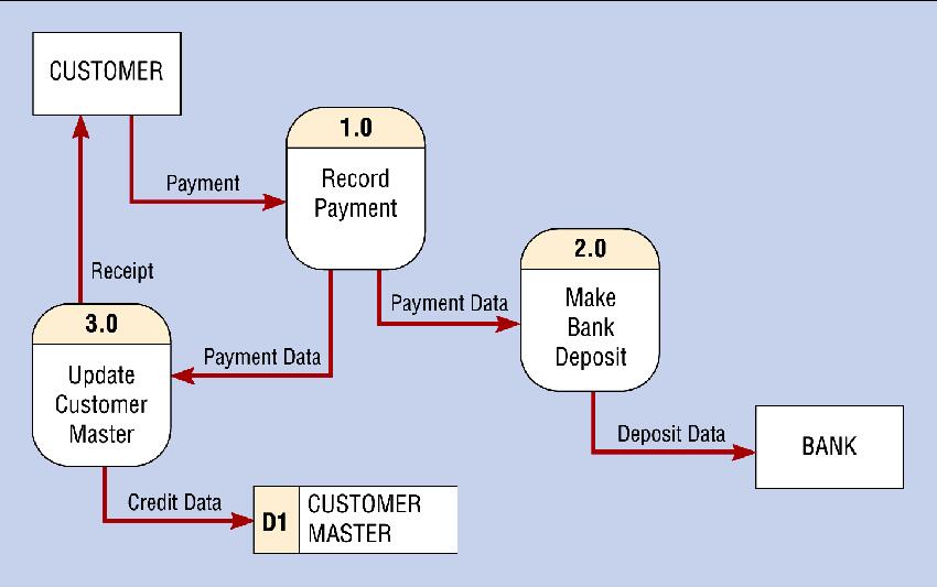
This example is a basic Level 0 of a Data flow Diagram. As you can see from the picture the rectangles represent external entities.

Ch.5 - Data and Process Modeling Flashcards | Quizlet
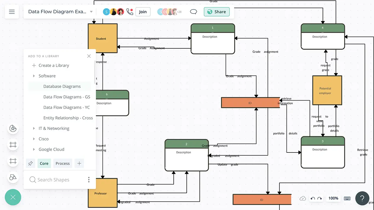
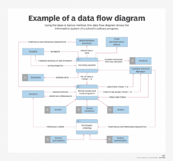
The CS System Data Flow Diagram example contains four processes, two external entities, and four data stores. Although there are no design guidelines that govern the positioning of shapes in a Data Flow Diagram, we tend to put the processes in the middle and data stores and external entities on the sides to make it easier to comprehend.

Example of Level 0 Data Flow Diagram | Download Scientific ...
Q.4 In a DFD external entities are represented by a A) Rectangle B) Ellipse C) Diamond-shaped box D) Circle. ... Q.8 A data flow can A) Only emanate from an external entity B) Only terminate in an external entity C) May emanate and terminate in an external entity
What is the Difference Between DFD and Flowchart - Pediaa.Com
External Entity – Also known ... diagrammed. These data flows are the inputs and outputs of the DFD. Since they are external to the system being analyzed, these entities are typically placed at the boundaries of the diagram. They can represent another system or indicate ...
How to Use Data Flow Diagrams to Model and Analyze BI ...
The flow from the warehouse usually ... and the flow to the warehouse usually expresses data entry or updating (sometimes also deleting data). Warehouse is represented by two parallel lines between which the memory name is located (it can be modeled as a UML buffer node). ... The Terminator is an external entity that communicates ...

How Data Flow Diagrams (DFD's) operate… | Eternal Sunshine of ...
Quiz | DFD – backstreetcoder
Comparison of Diagramming Tools

Data Flow Diagram Symbols, Types, and Tips | Lucidchart
What is a data store in a data flow diagram? - Quora
What is a Data Flow Diagram (DFD)?
Types and Components of Data Flow Diagram (DFD) - GeeksforGeeks
0 Response to "35 in a data flow diagram external entities are represented by"
Post a Comment