36 phasor diagram of rlc circuit
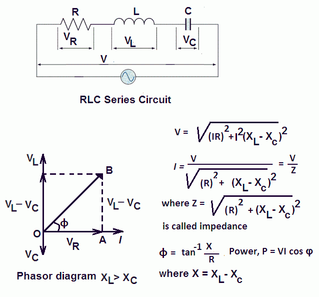
What is RLC Series Circuit? - Phasor Diagram... - Circuit Globe The phasor diagram of the RLC series circuit when the circuit is acting as an inductive circuit that means (VL>VC) is shown below and if (VL< VC) the circuit will behave as a capacitive circuit. Steps to draw the Phasor Diagram of the RLC Series Circuit. Phasor Diagram RLC Series AC Circuit | Physics Forums Related Threads on Phasor Diagram RLC Series AC Circuit. Engineering Parallel RLC circuit phasor diagram. Last Post.
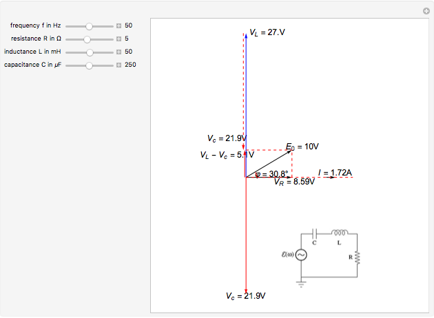
Driven RLC Circuit Using Phasors - GeoGebra This simulation shows the phasor representation of a series RLC circuit. Adjust the values of R, L, and C using the sliders. Change how the circuit is driven by adjusting the emf amplitude and driving frequency. Use the check boxes to select which graphs are shown.
Phasor diagram of rlc circuit
Phasor Diagram for Series RLC Circuits - Wolfram Demonstrations... This Demonstration shows a phasor diagram in an AC series RLC circuit. The circuit consists of a resistor with resistance , an inductor with inductance , and a capacitor with capacitance . The current in an RLC series circuit is determined by the differential equation. Phasor Diagram for a Parallel RLC Circuit Like the series RLC circuit, we can solve this circuit using the phasor or vector method but this time the vector diagram will have the voltage as its reference with the three current vectors plotted with respect to the voltage. The phasor diagram for a parallel RLC circuit is produced by combining... Phasor diagrams and RLC curcuits | All About Circuits | Forum I've got a series RLC circuit where I've been asked to find the phase angle φ and the generator voltage. several phasor diagrams can be plotted. and the nice thing is that once theta is found for one, it will be the same for all. imagine an x y graph: x axis on horizon with positive to the right, and y...
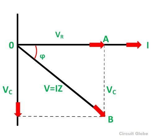
Phasor diagram of rlc circuit. PDF RLC Circuits RLC Circuits. It doesn't matter how beautiful your theory is, it doesn't matter how smart you are. If it doesn't agree with experiment, it's wrong. Richard Feynman (1918-1988). OBJECTIVES To observe free and driven oscillations of an RLC circuit. THEORY. The circuit of interest is shown in Fig. Phasor diagram for a series RLC circuit Drawing of the phasor diagram for a series RLC circuit energized by a sinusoidal voltage showing the relative position of current, component voltage and applied voltage for the following case. Consider a circuit in which R, L, and C are connected in series with each other across ac supply as shown in fig. web.mit.edu › viz › EMChapter 12 Alternating-Current Circuits (b) Phasor diagram for the resistive circuit. The behavior of IR (t)and can also be represented with a phasor diagram, as shown in Figure 12.2.2(b). A phasor is a rotating vector having the following properties: VR (t) (i) length: the length corresponds to the amplitude. (ii) angular speed: the vector rotates counterclockwise with an angular ... RL Circuit : Working, Phasor Diagram, Impedance & Its Uses Phasor Diagram of Series Circuit. The following steps give instructions step by step to draw the phasor diagram. The Parallel RL circuit phasor diagram is shown below. In the case of a parallel circuit, the flow of current within every branch of a circuit performs independently of the currents...
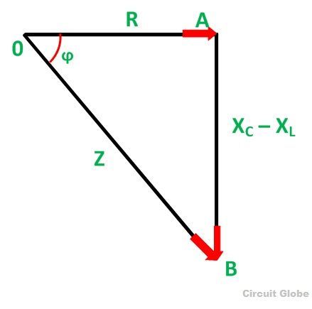
PDF Single Phase AC Circuits The phasor diagram of the RLC Series Circuit when the circuit is acting as an inductive circuit that means (VL>VC) is shown below and if (VL From the phasor diagram, the value of phase angle will be: ( ) ,,,, There are three cases of RLC Series Circuit: · When XL > XC, the phase angle ϕ is positive. Series RLC Circuit: Analysis and Example Problems Consider the circuit consisting of R, L and C connected in series across a supply voltage of V (RMS) volts. The resulting current I (RMS) is flowing in the circuit. For the convenience of the analysis, the current can be taken as reference phasor. Phasor Diagram For Rlc Series Circuit скачать с mp4 mp3 flv Phasor Diagram of Series RLC Circuit. 8:07. › rl-circuit-derivationRL Circuit : Derivation, Response Factors, Phasor Diagram and ... Jul 23, 2021 · To draw a phasor diagram for the circuit, below are the steps to be followed. Consider, the current ‘I’ as a reference point; The voltage drop that takes place across resistor V R = I R is drawn in the exact phase with that of current ‘I’.
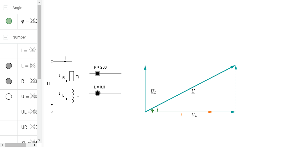
Series RLC Circuit — Collection of Solved Problems Series RLC Circuit. Task number: 1540. An AC circuit is composed of a serial connection of: a resistor with resistance 50 Ω, a coil with inductance 0.3 H. A phasor is an "arrow" that we use to plot the current and voltage values on individual components of the circuit into a phasor diagram. electric-shocks.com › rlc-series-circuit-phasorRLC Series circuit, phasor diagram with solved problem RLC Series circuit contains a resistor, capacitor, and inductor in series combination across an alternating current source. Before going further, I would like to take the current phasor as a reference. Because the current is the same in all the components of the RLC series circuit. passive networks - Phasor diagrams for RLC series circuit? How can I make phasor diagrams for the circuit in case when $$I_CI_L$$. The sign of the imaginary part will tell you if the circuit is predominantly inductive or predominantly capacitive . And hence if the current will lag the voltage or lead the voltage respectively. RLC Series AC Circuits | Physics Draw the circuit diagram for an RLC series circuit. Explain the significance of the resonant frequency. How does an RLC circuit behave as a function of the frequency of the driving voltage source? Combining Ohm's law, Irms = Vrms/Z, and the expression for impedance Z from [latex]Z...
Capacitive load and simplified equivalent circuit. The phasor ...
Phasor Diagram for Series RLC Circuits This Demonstration shows a phasor diagram in an AC series RLC circuit. The circuit consists of a resistor with resistance. . The current in an RLC series circuit is determined by the differential equation.
What is RLC Series Circuit? - Phasor Diagram & Impedance ...
RLC circuit - Wikiversity A RLC circuit (also known as a resonant circuit, tuned circuit, or LCR circuit) is an electrical circuit consisting of a resistor (R), an inductor (L), and a capacitor (C), connected in series or in parallel. This configuration forms a harmonic oscillator. Tuned circuits have many applications particularly for...
Series RLC Circuit (Circuit & Phasor Diagram) | Electrical4U
impedance of RLC circuit from phasor | Electronics Forum... For example, I have a RLC series circuit like this: And here is the phasor diagram to calculate impedance of...
In an R-l-c Parallel Circuit the Current Through the Resistor ...
Phasor Diagrams | Brilliant Math & Science Wiki | Phasor of a circuit Phasor diagrams are a representation of an oscillating quantity as a vector rotating in phase space with an angular velocity equal to the angular frequency of the Phasor diagrams are used in simple harmonic motion and RLC circuits which have elements that are out of phase with one another and …

a) Series connection of L C circuit and (b) its phasor ...
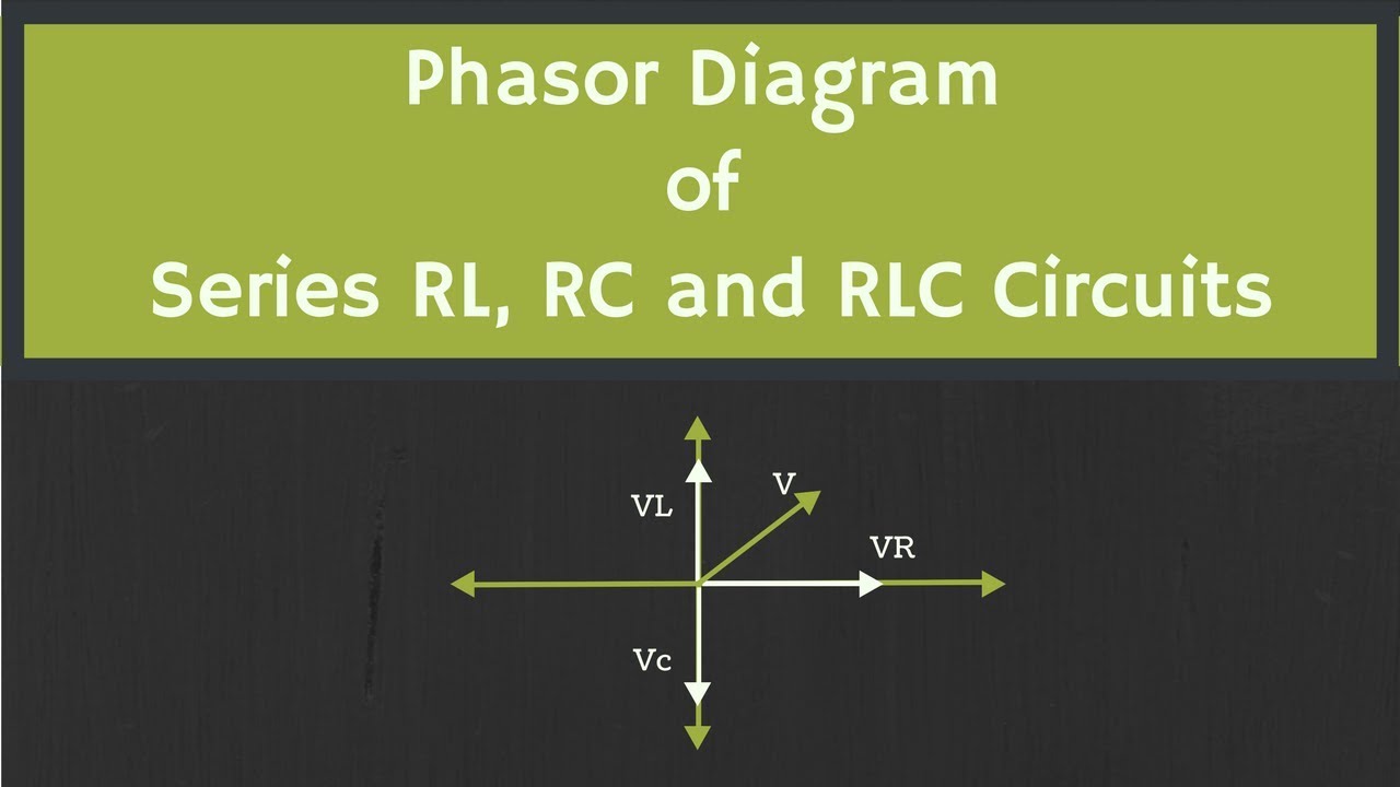
Phasor Diagram of Series RLC Circuit The NOTE: For remembering the phase relationship between voltage and current, learn this simple word called 'CIVIL', i.e in capacitor current leads voltage and voltage leads current in inductor. RLC circuit - For drawing the phasor diagram of series RLC circuit, follow these steps: Step - I...
RC | RLC | RL Series Circuits - your electrical guide
Series RLC Circuit | Analysis | Phasor Diagram | Impedance Triangle A series RLC circuit contains elements of resistance, inductance, and capacitance connected in series with an AC source, as shown in Figure 1. The three voltages of a series RLC circuit are combined, as shown in the circuit voltage vector (phasor) diagram of Figure 2 and constructed as follows
Phasor Diagram of RL, RC and RLC Circuits (with Examples)
RLC Series Circuit The RLC series circuit is a very important example of a resonant circuit. It has a minimum of impedance Z=R at the resonant frequency, and the phase angle is equal to The phasor diagram shown is at a frequency where the inductive reactance is greater than that of the capacitive reactance.
Solved 1. This is the phasor diagram for an RLC circuit with ...
Phasor Diagram - an overview | ScienceDirect Topics The purpose of a phasor diagram is to provide an efficient graphical way of representing the steady-state inter-relationship between quantities that vary Summarizing, when an RLC circuit is in a state of series resonance: • the circuit behaves as a pure resistance; • the inductive reactance is equal to...

USE OF ICT IN EDUCATION FOR ONLINE AND BLENDED LEARNING-IIT ...
Phasor - Wikipedia An example of series RLC circuit and respective phasor diagram for a specific ω. The arrows in the upper diagram are phasors, drawn in a phasor diagram (complex (calculation) of the AC steady state of RLC circuits by solving simple algebraic equations (albeit with complex coefficients) in the...

Phasor Diagram of Series RLC Circuit The
circuitglobe.com › three-phase-transformerThree-Phase Transformer Connections - Circuit Globe The phasor diagram of the ∆-Y connection of the three phase transformer is shown in the figure below. It is seen from the phasor diagram that the secondary phase voltage V an leads the primary phase voltage V AN by 30°. Similarly, V bn leads V BN by 30º and V cn leads V CN by 30º.This connection is also called +30º connection.
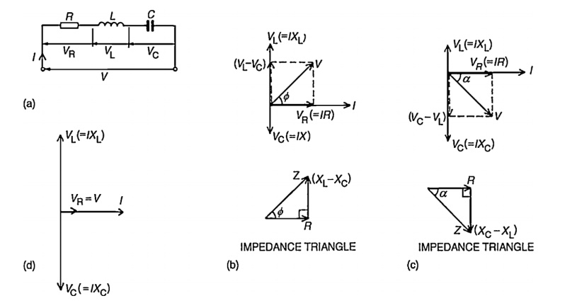
Phasor diagram for a series RLC circuit
Series RLC Circuit (Circuit & Phasor Diagram) | Electrical4U The phasor diagram of series RLC circuit is drawn by combining the phasor diagram of resistor, inductor and capacitor. Before doing so, one should understand the relationship between voltage and current in case of resistor, capacitor and inductor.
Series RLC Circuit (Circuit & Phasor Diagram) | Electrical4U
Chapter 12.3 - Phasor Diagram of Series RLC Circuit | Engineering360 The nature of the phasor diagram of a series RLC circuit depends on the frequency f of the applied signal in relation to the frequency of resonance f0. Three different cases may be considered: (i) f = fr, (ii) f < fr, and (iii) f > fr. with f = f0, the reactance XL of inductor L equals the reactance of capacitor C.

Phasor diagram for LRC circuit
circuitglobe.com › capacitor-start-induction-motorCapacitor Start Induction Motor - its Phasor Diagram ... A centrifugal switch S C is also connected to the circuit. The Phasor Diagram of the Capacitor Start motor is shown below: I M is the current in the main winding which is lagging the auxiliary current I A by 90 degrees as shown in the phasor diagram above. Thus, a single-phase supply current is split into two phases.

Figure 7.2 from Resonance and Impedance Matching 7.1 ...
Phasor Diagram of Series RLC Circuit - YouTube Phasor Diagram of Series RLC Circuit. Смотреть позже.

Series RLC Circuit and RLC Series Circuit Analysis
Series RLC Circuit Consider the RLC circuit in figure 1. There are at least two ways of thinking about it. One way is to treat it as a real (noisy) resistor Rx in series with an inductor and capacitor. Figure 1: Series RLC Circuit, Grounded Capacitor. We start by applying Ohm's law for complex impedances The phasor current is

The phasor diagram for an RLC circuit driven by an AC source ...
Phasor Diagrams and Phasor Algebra - Electronics-Lab.com A phasor diagram consists of the same figure as presented above but with two or more vectors. Phasor diagrams are very convenient when we need to add and subtract two signals that are not in fig 7: Differentiated and integrated phasors in a phase diagram. Consider an RC series circuit in...
Using Phasor Diagrams to Evaluate Series and True Parallel RLC AC Circuits
Phasor diagrams and RLC curcuits | All About Circuits | Forum I've got a series RLC circuit where I've been asked to find the phase angle φ and the generator voltage. several phasor diagrams can be plotted. and the nice thing is that once theta is found for one, it will be the same for all. imagine an x y graph: x axis on horizon with positive to the right, and y...

Series RLC Circuit and RLC Series Circuit Analysis
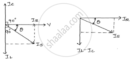
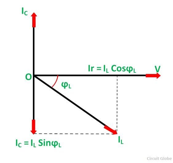
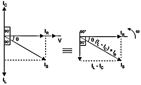
Phasor Diagram for a Parallel RLC Circuit Like the series RLC circuit, we can solve this circuit using the phasor or vector method but this time the vector diagram will have the voltage as its reference with the three current vectors plotted with respect to the voltage. The phasor diagram for a parallel RLC circuit is produced by combining...

Phasor Diagram - an overview | ScienceDirect Topics
Phasor Diagram for Series RLC Circuits - Wolfram Demonstrations... This Demonstration shows a phasor diagram in an AC series RLC circuit. The circuit consists of a resistor with resistance , an inductor with inductance , and a capacitor with capacitance . The current in an RLC series circuit is determined by the differential equation.
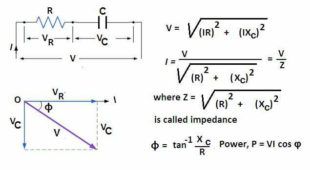
What is RC Series Circuit? Phasor Diagram and Power Curve ...

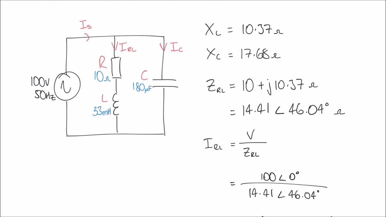
RLC Series circuit, phasor diagram with solved problem

Phasor diagram - RLC series circuit
Draw vector diagram (phasor diagram) for a series RLC circuit ...
Chapter 12.3 - Phasor Diagram of Series RLC Circuit ...

RLC Series Circuit - Engineering Notes Online
Phasor Diagram - RL Series Circuit – GeoGebra

Series RLC Circuit and RLC Series Circuit Analysis
RC | RLC | RL Series Circuits - your electrical guide
![Solved] The phasor diagram for an RLC circuit is shown in ...](https://s3.amazonaws.com/si.question.images/image/images15/1307-P-M-P-Q-M(1118).png)
Solved] The phasor diagram for an RLC circuit is shown in ...
Phasor Diagram for Series RLC Circuits - Wolfram ...

Series RLC Circuit and RLC Series Circuit Analysis

Phasor diagram - LCR circuit - For Xc greater than XL / Capacitive reactance greater than inductive
What is Parallel Resonance? Effect of Frequency & Phasor ...
RLC Circuit -RLC in Parallel – microdigisoft.com
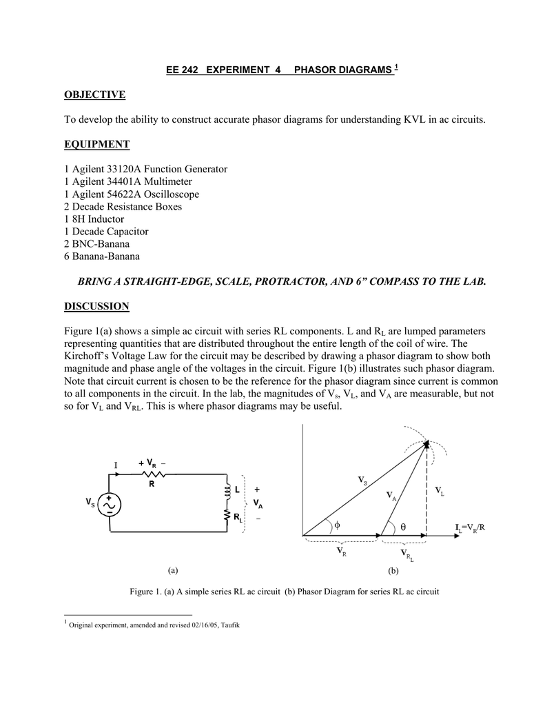
OBJECTIVE To develop the ability to construct accurate phasor
RLC Series Circuit
0 Response to "36 phasor diagram of rlc circuit"
Post a Comment