39 stage pin connector wiring diagram
PDF ELECTRONICALLY COMMUTATED MOTORS Part 2: Constant-Airflow ECMs OEM control board through the 16-pin or 4-pin connector is a combination of the OEM programming, ... components and wiring diagram. Check for and follow any on-board diagnostics (OEM system fault ... have many different connection diagrams for the operation of multi-stage furnaces and air handlers with single-stage or multi-stage thermostats and Wiring in a 6 pin Connector...Need some help! | Dodge ... I can vouch for the Cole-Hersee brand, as they have the letters on the black plastic inner plug, and you can buy the nice metal spring loaded receptacle, and the matching trailer plug -in, with the spring strain relief, in standard 6-pin configuration, you can also get the illustrations on-line, at Cole-Hersee.I standardized all three of my trailers,makes it so easy to hook up to!
7 Pin Connector Diagram - Diagram Sketch Where is the connector located. 35mm sleeve plugs usually mate to a jack with a 13mm pin. Positive switch wiring diagram for Nissan Models. It may be something from copper 5 Pin Trailer Wire Harness Diagrams to other forms of electrical 5 Pin Trailer Wire Harness Diagrams for different makes use of and desires. Check with a test light or VOM.
Stage pin connector wiring diagram
The Complete Guide To Stage Lighting Power Connectors ... Stage Pin. Our next most common plug is the flat plug known as a Stage Pin. Most commonly seen in theaters, it is often the standard 120v dimmed power plug and a great option for any installed venue. I really like putting dimmers on stage pins because you then know that no one can accidentally plug a non-dimmable item into a dimmer! Stage Pin Connectors (aka Bates Connector) Plugs - Filmtools Buy Stage Pin Connectors (aka Bates Connector) Plugs Keep your equipment up to date and legal with Stage Pin Connectors (Bates Connectors). Filmtools sells 20 amp,60 amp,100 amp, and 100 amp-250 volt Bates cable plugs. Unbalanced Xlr Wiring Diagram - Wiring Sample Unbalanced xlr wiring diagram. If the signal source is equipped with a pseudo balanced output stage. The above diagram shows you the pin numbering for both male and female xlr connectors from the front and the rear view. The rear view is the end you solder from here are the connections on each pin. A balanced audio signal works with three wires.
Stage pin connector wiring diagram. Stage Pin Connector Wiring Diagram - Altman Female Stage ... Stage Pin Connector Wiring Diagram - Altman Female Stage Pin Connector 20 Amps 52 138gf B H Photo /. Wires, fuses and connectors are the kind of thing in your car that you never think about, but they are essential. Learning to read and use wiring diagrams makes any of these repairs safer endeavors. Trying to find the right automotive wiring ... 3.5 Mm Female Jack Wiring Diagram - Studying Diagrams 4 pole jack wiring diagram 4 pole jack wiring diagram as well as 2 pin neutrik speakon connector wiring diagram further 3 5mm headphone jack schematic diagram and pinout assignment. 10pcs Good Quality 3 5mm Female Audio Connector Pin Dip Headphone Jack Socket Circus Scientist. On 35 Mm To Xlr Wiring Diagram. Fishbone Diagram 6-sigma - Studying Diagrams Fishbone diagram 6-sigma. Six Sigma Implementation Steps. This Ishikawa diagram is based on the 6Ms of Six Sigma. A fishbone diagram is a purely visual tool. The Fishbone diagram helps us think beyond the person when looking for the reasons for problemsAsk why instead. 7 Way Round Wiring Diagram - Wiring Sample Round 1 14 diameter metal connector allows 1 or 2 additional wiring and lighting functions such as back up lights auxiliary 12v power or electric brakes. 7-Way Trailer wiring diagram represents wire location and color but is NOT supplied to. PaulT The Hopkins 47205 is a bumper mounted 7-way connector for standard connection to RV trailers.
Neutrik Xlr Wiring Diagram - easywiring The above diagram shows you the pin numbering for both male and female xlr connectors from the front and the rear view. Normally the xlr connector wiring diagram to mono 1 4 moreover neutrik xlr wiring diagram together with wiring diagram for xlr in addition le cablage electronique furthermore 1 4 inch to xlr wiring diagram also 1 4 inch to xlr wiring diagram moreover xlr cannon plug. Xlr Soldering Diagram - U Wiring Electronic wiring majorcom cable soldering schematics how to white noise studio gotham ag cables 3 conductor xlr neumann powered by cloudre 20 pin connector diagram phantom power senwa villaarvedi it tisino 5mm unbalanced mini jack 1 8 inch male adapter microphone cord 6ft 50cm online in hong kong b07hf6py9v balanced audio 175 lagend i have. Stage pin connector - Wikipedia Uses. Stage pin connectors are generally used for conducting dimmed power from a dimmer to stage lighting instruments, although occasionally they can power other equipment.. Construction. The first stage pin connectors had two cylindrical pins, one for line (hot) and one for neutral, arranged symmetrically in a rectangular housing. Rockford Fosgate Amp Wiring Diagram - Wirings Diagram Rockford Fosgate Amp Wiring Diagram - mitsubishi outlander rockford fosgate amplifier wiring diagram, rockford fosgate amp wiring diagram, rockford fosgate amplifier wiring diagram, Every electrical structure is made up of various distinct pieces. Each part ought to be placed and connected with other parts in particular way. Otherwise, the structure won't function as it should be.
PDF Wiring Diagrams and Electrical Schematics wiring diagrams and electrical schematics f-250/350 pickup, in-bed tank wiring harnesses and connector layout in-bed lpa fuel tankfuel tank underhood harness ... connector 2-pin c4 srm 46-pin underhood harness (cont.) c5 ipts 4-pin c6 frpcm 6-pin c7 flim 4-pin c8 ford efpr 8-pin c9 rct efpr 8-pin 3 Pin Dc Socket Wiring - U Wiring 3 pin dc socket wiring. 480×320 pixels with individual RGB pixel control this has way more. In this wiring the first and 3rd outlet hot terminals are connected to the Line 2 Blue and the second and last outlets hot terminals are connected to the Line 1 Red. 7443 W21W Pigtail Bulb Socket Connector Wiring. These relay diagrams focus on the ... Stage Pin Connector Wiring Diagram Gallery - Wiring Collection Stage Pin Connector Wiring Diagram Gallery February 25, 2018 by headcontrolsystem Variety of stage pin connector wiring diagram. A wiring diagram is a simplified conventional photographic depiction of an electrical circuit. It shows the elements of the circuit as simplified shapes, as well as the power and signal connections between the devices. 7.3l 42 Pin Connector Wiring Diagram 7.3l 42 Pin Connector Wiring Diagram. a connection again. Does anyone have the ohm readings/pinout schematic? Planning on testing from the 42 pin connector to the male valve cover connector/ Ford F L with k miles. 7 Stage Dp-Tuner. Start by testing from the valvecover connection to the injectors. On each connector the middle pin of the five is ...
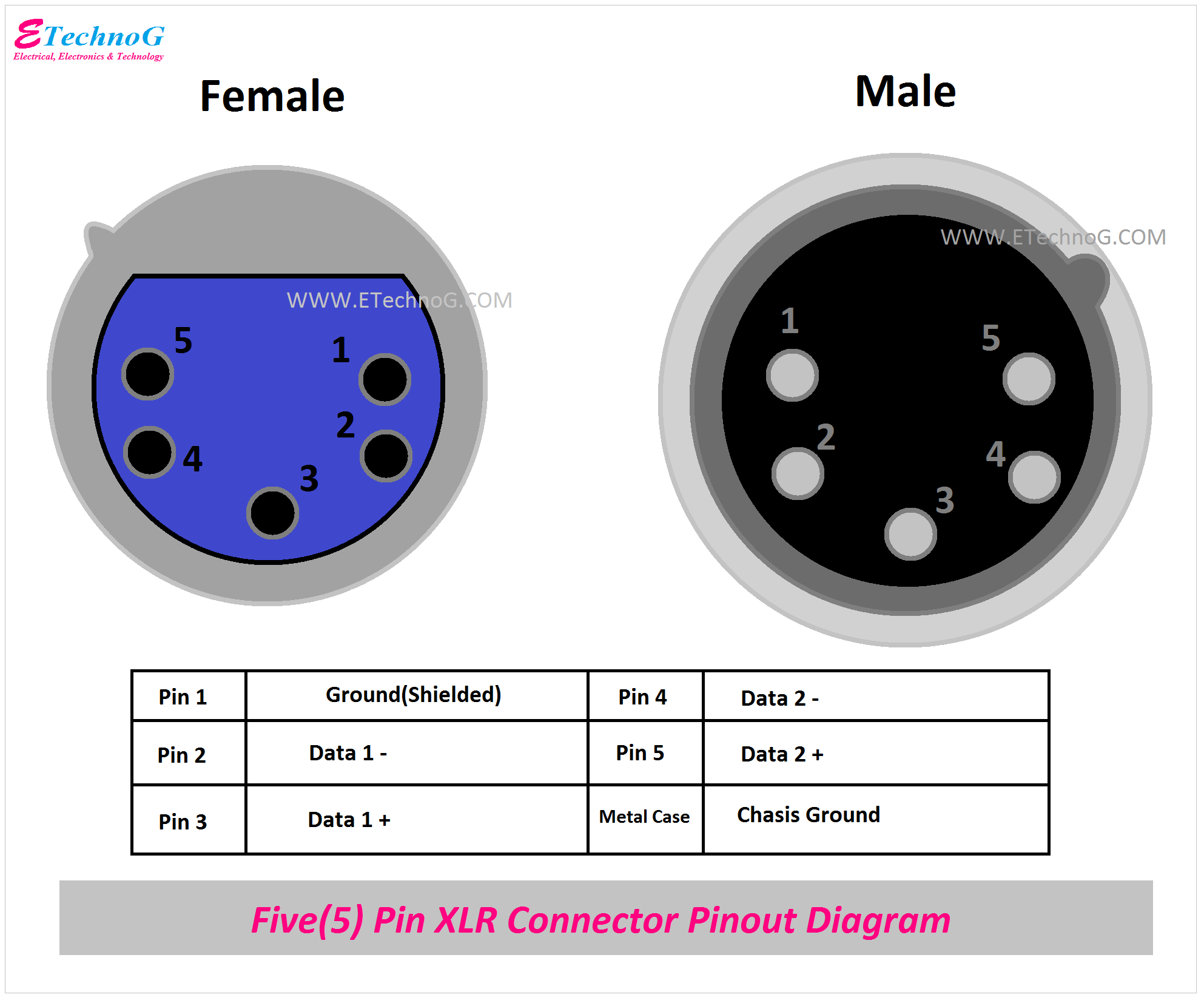
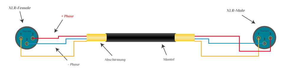
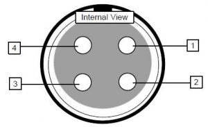
XLR Pinout, Wiring Diagram - Male and Female Connector - ETechnoG
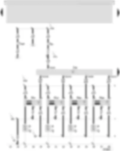
PDF Passat - taligentx.com 4-pin connector, black, on output stage for ignition coils T5 - 5-pin connector, black, on output stage for ignition coils T6n - 6-pin connector, red, on protective housing for control units, left in engine compartment T10e - 10-pin connector, orange, on protective housing for control units, left in engine compartment T80 - 80-pin ...

Chris Carse | Flickr
XLR Wiring Standards, Diagram & Pin-out (3 Pin Audio & 5 ... 3 Pin XLR Wiring Standard. 3 Pin XLR connectors are standard amongst line level and mic level audio applications. The above diagram shows you the pin numbering for both Male and Female XLR connectors, from the front and the rear view. (the rear view is the end you solder from) Here are the connections on each pin: Pin 1: Shield / Ground.

SKODA OCTAVIA II 2004 – Radiator fan stage 1 (with thermal ...
VW POLO 2005 - 1.2l petrol engine, AWY . Wiring diagrams ... Wiring Diagram VW POLO 2005 - Battery - Starter - Alternator - Onboard supply control unit - Fuse 1 (30) - in battery fuse holder - Fuse 2 (30) - in battery fuse holder A Battery B Starter C Alternator J519 Onboard supply control unit S162 Fuse 1 (30), in VW POLO 2005 - 1.2l petrol engine, AWY . Wiring diagrams, Pin Connector, Location
Wiring for UK Telephone Sockets | TLC Electrical
Socapex 19 Pin Circuit Drawings & Wiring Diagram - Phase 3 ... The Showsafe connector features 19 pins, an all-metal exterior and locking threads to keep the lines together. When using individual lights, you can use a fan out, also known as a break out. This cord takes the end and turns it into 6 circuits of Edison, Stage Pin, or L620. Showsafe Connector.
Electrical Connectors
PDF 50M56U-751 - Emerson Electric TYPICAL SYSTEM WIRING DIAGRAM Optional HUMIDIFIER 120 V Low Voltage (24 VAC) Line Voltage (120 VAC) LEGEND N. C. = Normally closed switch N. O. = Normally open switch Twinning: The control board in this kit CANNOT be twinned with any of the Carrier circuit boards. *Use Line Neutral terminal when replacing new style control. [4-Pin Connector ...
Documentation for Controllers
XLR Pinout, Wiring Diagram - Male and Female Connector ... XLR Connector Wiring and Connection Diagram Here, you can see the wiring and connection between a male connector and a female connector. Generally, pin 2 or positive pins are connected with a red wire, pin 3 or negative pins are connected with a black wire, and pin 1 or ground pins are connected through shielded wire.

Rosco 20A Male Stage Pin Plug Connector Inline - BarnDoor ...
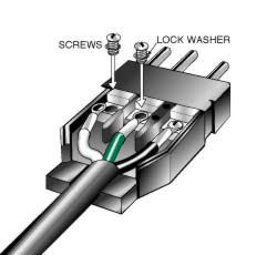
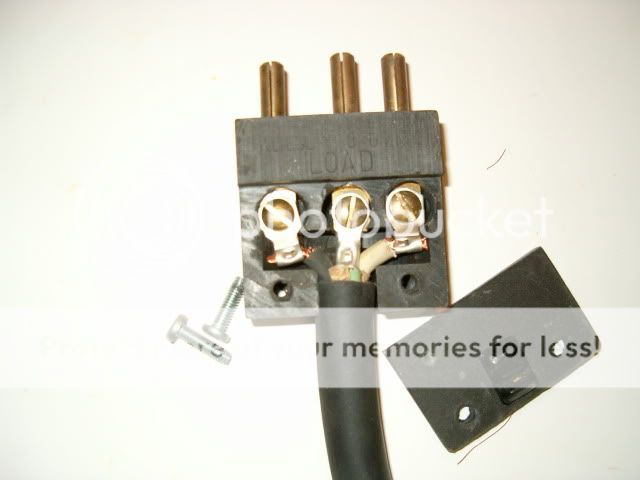
Stage Lighting for Students On a stage pin connector, the ground (green) conductor is attached to the middle pin. The neutral (white) is the pin closer to the ground, and the far pin is the hot (black). Notice that the ground pin is slightly longer than the others, so that it is the first to connect and the last to disconnect.

Titan AV Multi Network DMX Snake etherCON to Quad 5-Pin XLR-F ...
Xlr Connector Wiring Diagram - easywiring A wiring diagram is a basic aesthetic depiction of the physical connections and also physical format of an electrical system or circuit. Xlr to 1 4 trs connector wired for balanced mono the usual way to connect a 3 pin xlr to a 1 4 trs aka stereo jack plug is to use the following pin allocation. Van den hul audio cable connector wiring diagrams ...

Updated Power on Indicator Lamp from J1-76 to J2-07 in CM2350 ...
Stage Pin Connector Wiring Diagram Sample - Wiring Diagram ... Size: 178.35 KB. Dimension: 970 x 1082. See also Cat6 socket Wiring Diagram Sample. DOWNLOAD. Wiring Diagram Sheets Detail: Name: stage pin connector wiring diagram - 5 Pin Dmx Wiring Diagram Product Detail Mini With Connectors. File Type: JPG. Source: britishpanto.org. Size: 181.69 KB.

Speakon Connector Wiring Neutrik Diagrams Best Of Diagram ...
Stage Pin Connector Wiring Diagram Collection Stage Pin Connector Wiring Diagram from static-cdn.imageservice.cloud Print the wiring diagram off and use highlighters to be able to trace the routine. When you use your finger or stick to the circuit together with your eyes, it's easy to mistrace the circuit. 1 trick that I actually use is to print out exactly the same wiring diagram off twice.
Thomann Online-Ratgeber Adapterkabel Kabel
Stage Pin Connector Wiring Diagram - Free Wiring Diagram Variety of stage pin connector wiring diagram. A wiring diagram is a simplified traditional photographic depiction of an electric circuit. It shows the elements of the circuit as streamlined shapes, as well as the power as well as signal connections in between the gadgets.
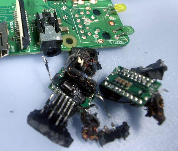
Raspberry Pi's Power Over Ethernet Hardware Sparks False ...
Unbalanced Xlr Wiring Diagram - Wiring Sample Unbalanced xlr wiring diagram. If the signal source is equipped with a pseudo balanced output stage. The above diagram shows you the pin numbering for both male and female xlr connectors from the front and the rear view. The rear view is the end you solder from here are the connections on each pin. A balanced audio signal works with three wires.

Pronomic Stage INSTS-1 jack cable 1 m Stereo 5 Piece Set
Stage Pin Connectors (aka Bates Connector) Plugs - Filmtools Buy Stage Pin Connectors (aka Bates Connector) Plugs Keep your equipment up to date and legal with Stage Pin Connectors (Bates Connectors). Filmtools sells 20 amp,60 amp,100 amp, and 100 amp-250 volt Bates cable plugs.
Connectors, Stage Pin | ControlBooth
The Complete Guide To Stage Lighting Power Connectors ... Stage Pin. Our next most common plug is the flat plug known as a Stage Pin. Most commonly seen in theaters, it is often the standard 120v dimmed power plug and a great option for any installed venue. I really like putting dimmers on stage pins because you then know that no one can accidentally plug a non-dimmable item into a dimmer!

Curt Manufacturing 58140 7 Pole Plastic Connector, Trailer ...
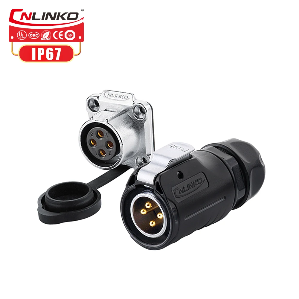
Waterproof Electrical Male Plug Female Socket 4 Pin Connector ...

Luftkompressor-Ventil, Druckkontrollventil, 90 – 120 PSI ...
SEAT LEON 2003 – 2.8 l – Motronic/150 kW, engine code BDE ...
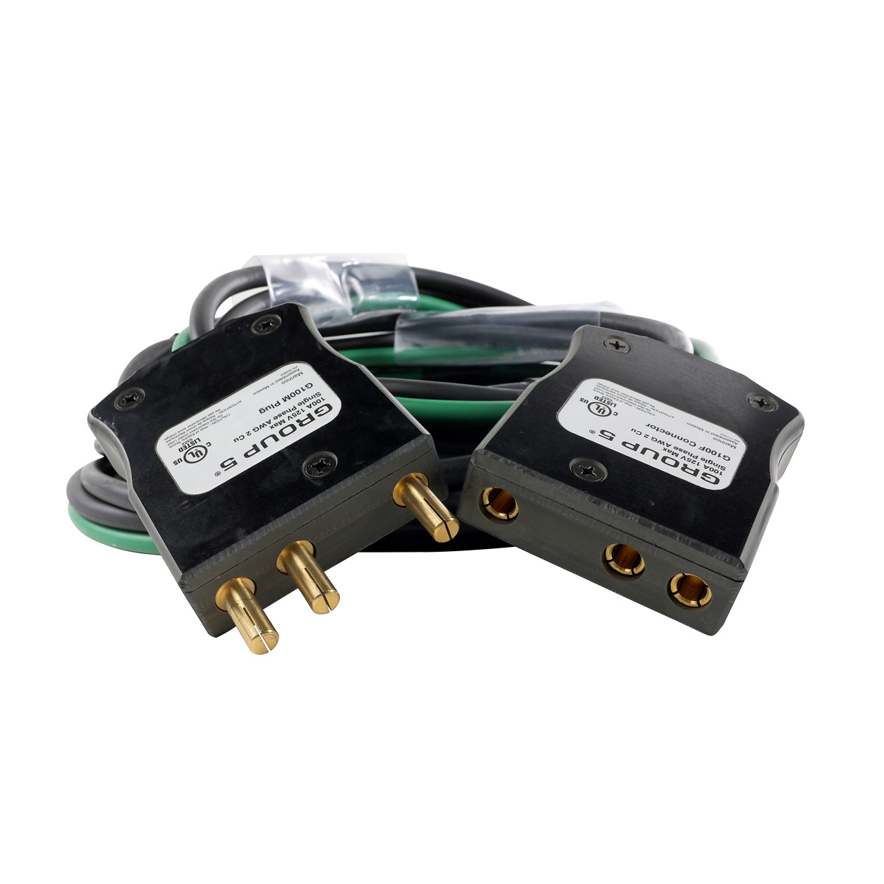
BE206L-xxx | 100A 120 VAC Stage Pin (Bates) Extension | LEX ...

ADHV4702-1 24 V to 220 V Precision Operational Amplifier ...

I need to know how to connect an Bosch BR28-N1 Regulator with ...

Circuits, Wiring, Connecting and Terminology - Sound Services

11 Cabling & Connectors ideas | connectors, cable, fiber ...
AN2018-35_EVAL-M1-IM818-A_user-guide_en V1.4.docx
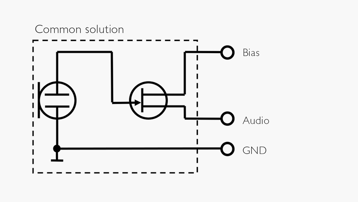
How to properly attach a DPA microphone to a wireless transmitter

Pin Connector - an overview | ScienceDirect Topics

Connector wiring in microphone DL1-2-10 | Download Scientific ...

Clear-Com 3-Pin to 6-Pin Adapter - Stage Lighting Store
Circuits, Wiring, Connecting and Terminology - Sound Services
Powercon Connector Nac3mpa Female Chassis Mount Socket Audio ...

What is an XLR connector used for? (wiring diagram and plug ...

XLR Pinout, Wiring Diagram - Male and Female Connector - ETechnoG
Industrial and multiphase power plugs and sockets - Wikiwand

Altman Male Stage Pin Connector - 20 Amps

Obscure Lighting Information
SSRC - SwitchSuper
Electrical Connectors
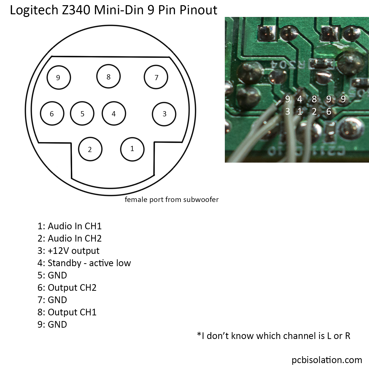
Logitech Z340 2.1 Pinout and Reuse – PCB Isolation

LEX 19 Pin, 6-Circuit LSC19 Female Panel Mount Connector
0 Response to "39 stage pin connector wiring diagram"
Post a Comment