37 timer relay wiring diagram
Wiring Diagram For 11 Pin Relays - Wiring Diagram Line Wiring Diagram For 11 Pin Relays Wiring Diagram Line Wiring Diagram. Wiring Diagram Line We are make source the schematics, wiring diagrams and technical photos ... Wiring octal 11 pin latching relay cr4 discussion thread and timer specifications technical data solid state electrical academia item 326xbx48p 010 115 125vdc 326 327 series time ... Automatic Star Delta Starter With Timer Wiring Diagram ... Star delta wiring diagram with timer are listed below. In the above star delta starter control circuit wiring diagram with timer and normally close push buttonnormally open push button switch. From l1 the phase current flows to thermal overload contact through fuse, then off push button, on push button interlocking contact 2, and then c3.
Timer Wiring Diagram Manual - Wiring Diagram and Schematic ... 2510sxt Wiring Diagram Hydrotech Sxt Timer User Manual Page 20 24 Original Mode. Eapl Model A1d1 On Power Application Preset Timing Starts And At. Clock Timer Wiring Diagram And Setting Home Appliances Parts Manual Spare By Type Online. Page 900 Motor Protection And Control Manual Starters Contactors Overload Relays.

Timer relay wiring diagram
PDF Timing Diagrams Overview Timers - IDEC Corporation Relays Sockets Timers Contactors Terminal Blocks Circuit Breakers 800-262-IDEC (4332) t SA & Canada 833 Timers Timing Diagrams Overview Cycle 1 (power start, OFF first) When voltage is applied to the coil, the contacts remain in the off state and the set time begins. At the end of the set time, the contacts transfer to the on state Contactor And Relay Wiring Diagram - The Wiring Single Pole Contactor Relay Wiring Diagram 240v Single pole means that it can only control a single circuit and single throw means that there are only two positions the switch can be in one on and one off state mechanical relays do not The esd5 series is an accurate solid state delayed interval timer it offers a 1a steady 10a inrush output and ... 12 Volt Relay Wiring Diagram - Wiring Diagram In addition, Wiring Diagram provides you with time body by which the tasks are to be completed. You will be able to know precisely if the projects needs to be finished, which makes it much easier for you to effectively handle your time. Multiple 12V Relay Wiring Diagram | Wiring Diagram - 12 Volt Relay Wiring Diagram
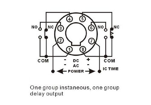
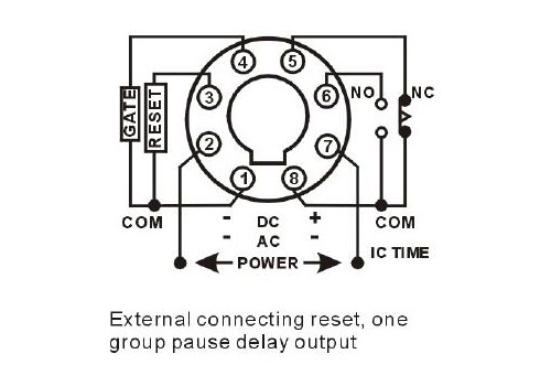
Timer relay wiring diagram. Adjustable Timer Circuit Diagram with Relay Output Mar 21, 2016 · The above proposed circuit is a 1-10 minute timer.When Pot is minimum it gives 1 minute delay,where maximum value of pot can produce 10 minutes. Time period can be calculated using formula T=(R1+R2)*C1.seconds When Pot is maximum R is 120K+1.1M ≈ 1.2M (approximately) and C1=470uf T= 1.2M*470uF = 620 seconds≈10 minutes.This is the maximum time. Ngk Lamp Timer Wiring Diagram Please look at this picture: relay wiring diagram. Make sure to. ngk lamp timer 12v dc wire diagram need dentifying what ih8mud forum bj60glow ngk lamp timer 12v dc wire diagram sony ireleast info oe replacement parts. timer how to wire this delay relay switch electrical these diagrams came the circuit. 8 Pin Relay Wiring Diagram - Wiring Diagram How To Wire Pin Timers - 8 Pin Relay Wiring Diagram. Wiring Diagram comes with several easy to stick to Wiring Diagram Directions. It is intended to aid all the common consumer in creating a proper system. These instructions will likely be easy to grasp and use. With this particular guide, you may be able to see how each and every component ... 8 Pin Timer Relay Wiring Diagram | Basic Timer Connection ... 8 Pin Timer Relay Wiring Diagram | Basic Timer Connection And Function |Three Phase Main Distribution Board Wiring | 3 Phase Distribution MDB Box Wiring Diag...
Relay Wiring Diagram: A Complete Tutorial | EdrawMax The diagram above is the 5 pin relay wiring diagram. There are different kinds of relays for different purposes. It can be used for various switching. Relay can be the best option to control electrical devices automatically. 5 pin is compromised of 3 main pins and an SPDT (single pole double throw). Automotive Relay Diagram! 4 & 5 Pin Relay Wiring Diagram Below is the wiring diagram of the four and five-pin car relay. 5-Pin-Relay-Wiring-Diagram-On-Relay-Case. According to DIN 72552 Standard, each pin of a relay is numbered 85, 86, 30, 87, and 87a. You need to know that a relay has two circuits, a coil circuit, and a high amperage circuit. In a relay 85 and 86 pins are considered coil circuit ... 11 Pin Relay Wiring Diagram - The Wiring Products related to D3RF3A General Purpose Relay, 11 Pin, 3PDT, 120V AC or visit the Eaton site. Need to wire in a Dayton 11 pin time delay relay to pull in a v contactor on a motor starter for it to run for a set time. Harley Davidson Shovelhead Wiring Diagram This is the Wiring […] 12v Timer Circuit Diagram - Wiring World 12v Timer Circuit Diagram. 12v Universal Heated Rear Window Timer Relay 10 Min Delay Timer Relay Digital Timer. One Transistor Relay Delay On Timer Circuit Electronic Circuit Design Circuit Projects Electronics Circuit. Basic Timer Control With 555timeric Circuit Is An Integratedcircuit Used In A Variety Of Timer Pulse Generati Devre Semasi ...
8 Pin Timer Relay Wiring Diagram - Diagram Sketch Contactor Wiring Diagram With Timer Diagram Relay Wire . How To Connection 8 Pin Timer Relay With Diagrams Timer Relay Connection . Te Connectivity 12v Dc Coil Non Latching Relay 3pdt 10a Switching Current Plug In Mt321012 6 1393091 8 Rs Components Electrical Projects Relay Electrical Circuit Diagram . Timing Relay Wiring Diagram - Wiring Diagram and Schematic ... Wiring diagram relay omron h3cr a8 solid state timer time delay relays to cycle a traffic signal 326 327 series on super circuit with 555 electromechanical double best factory dc 12v 24v chint jss48a Gambar 3 Wiring Diagram Relay Omron H3cr A8 Scientific Solid State Timer Relay Electrical Academia Using Time Delay Relays […] PDF Multi-functional Timer relay. voltage, the time relay (t) Upon application of input begins. At the end of the time delay (t), the output is energized. Input voltage must be removed to reset the time delay relay & de-energize the output. The timer function #1 is ON DELAY, it allows to supply power after a period of time (t). There are two off delay timer relay wiring diagram - IOT Wiring Diagram Dec 11, 2021 · Off Delay Timer Relay Wiring Diagram. By IOT | December 11, 2021. 0 Comment. Solid state timer relay electrical academia using time delay relays to cycle a traffic signal 555 ic motor control systems part c electromechanical worksheet digital circuits how wire an off dol starter overrun the for 5 minutes quora circuit before turn on working ...
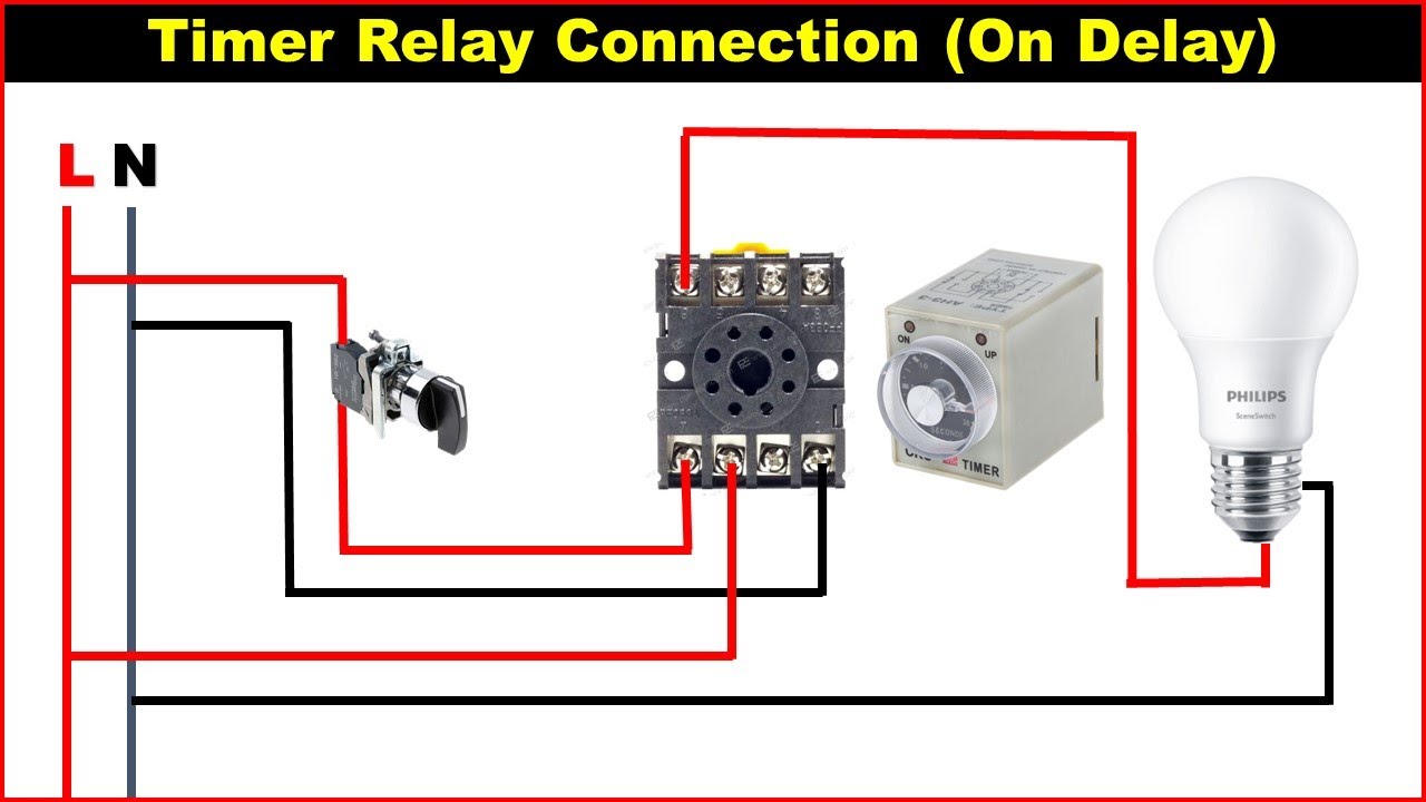
On Delay Timer Connection Diagram and Testing - ETechnoG
Timer Switch Diagram - easywiring The above circuit diagram is for the 1-minute timer circuit. This Touch Switch Circuit Diagram is built around a 555 timer by making use of the default properties of the Pins of the 555 Timer IC. This will give an output at Pin 2 after about 9 Hours. Wiring diagram for timer and contactorSterilmatic fails to operate at all.

Single Function Time Relay GRT8-A1 - GEYA
8 pin timer relay wiring diagram - YouTube A timer relay is a combination of an electromechanical output relay and a control circuit the contacts will open or close before or after a preselected timed...
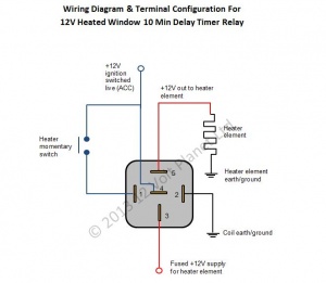
12V Universal Window Heater Timer Relay | 12 Volt Planet
Dayton Time Delay Relay Wiring Diagram | Diagram, Relay, Timer Dayton Time Delay Relay Wiring Diagram. Find this Pin and more on Electrical panel by Power7 Energy. Here is my newly wired panel. It took a very long time to get here with kids, moving, new house, new job. It is a 50amp Kal kit with a minor change...
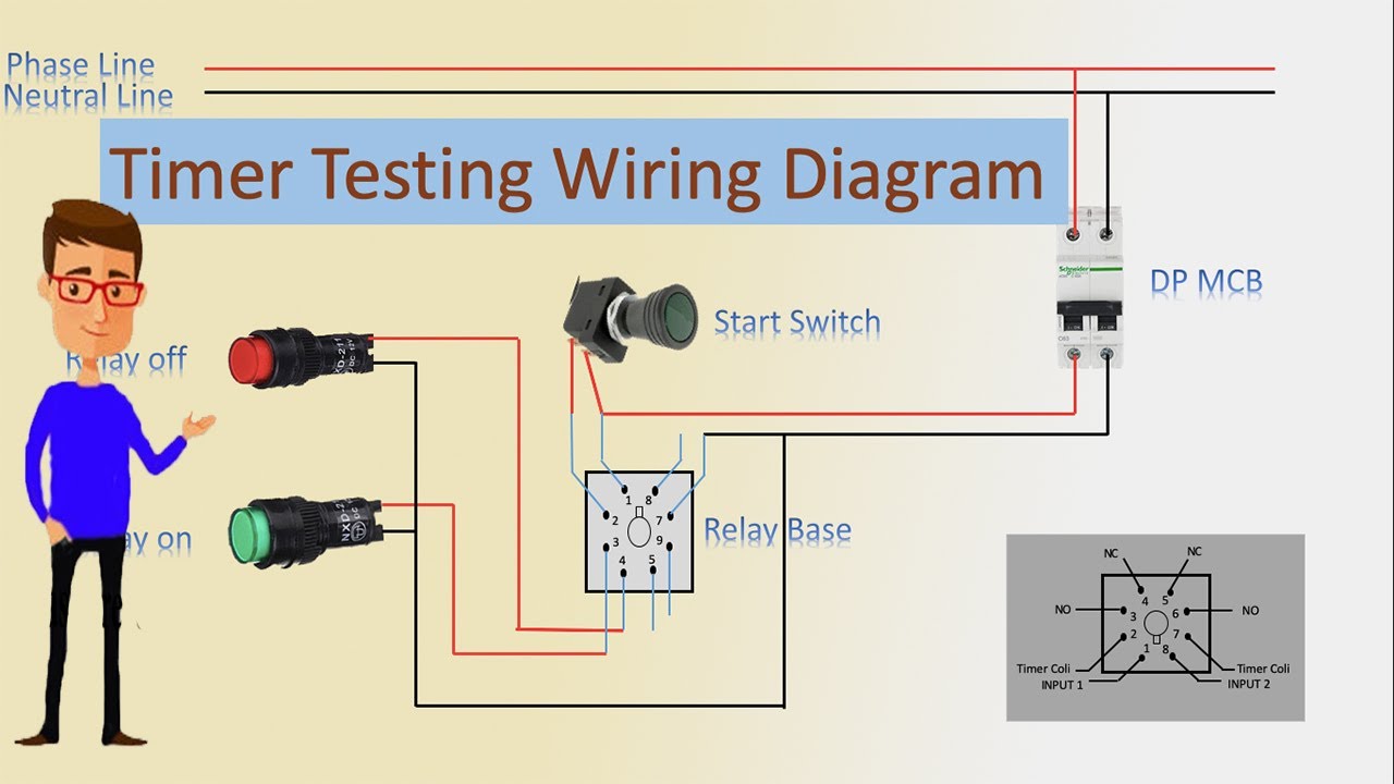
Timer Testing Wiring Diagram | Timer | Timer Wiring | Timer Wiring
Timer And Contactor Wiring Diagram Pdf - Wiring Diagram Timer And Contactor Wiring Diagram Pdf. 240 volts ac and 480 volts ac are commonly used for these large pieces of. Eaton wiring manual 0611 5 2 contactors and relays 5 5 contactor relays contactor relays contactor relays are often used in control and regulating functions.
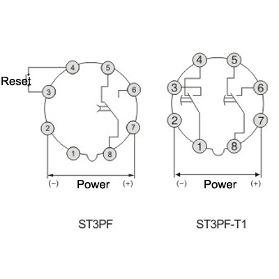
ST3PF time delay relay electronic general purpose relay ...
Dayton Time Delay Relay Wiring ... - Wiring Diagram Sample dayton time delay relay wiring diagram - What's Wiring Diagram? A wiring diagram is a schematic which uses abstract pictorial symbols to exhibit each of the interconnections of components in a very system.

On Delay Timer Connection Diagram and Testing - ETechnoG
Off Delay Timer Relay Wiring Diagram - U Wiring Off Delay Timer Relay Wiring Diagram. Amarante Pruvost. August 20, 2021. Find Instant Quality Info Now. Get Results from multiple Engines. This Post Is About The Staircase Timer Wiring Diagram In The Diagram I Use The On Delay Timer Finder 8 Pin Relay Re Electrical Circuit Diagram Timer Diagram.

Double Delay Time Relay, Best Factory Supplier in China - Geya
On Delay Timer Connection Diagram and Testing ... May 17, 2021 — Here, you can see the terminal diagram of on delay timer in the below figure. ... Here, you can see total of eight terminals is there. A1 and A2 ...

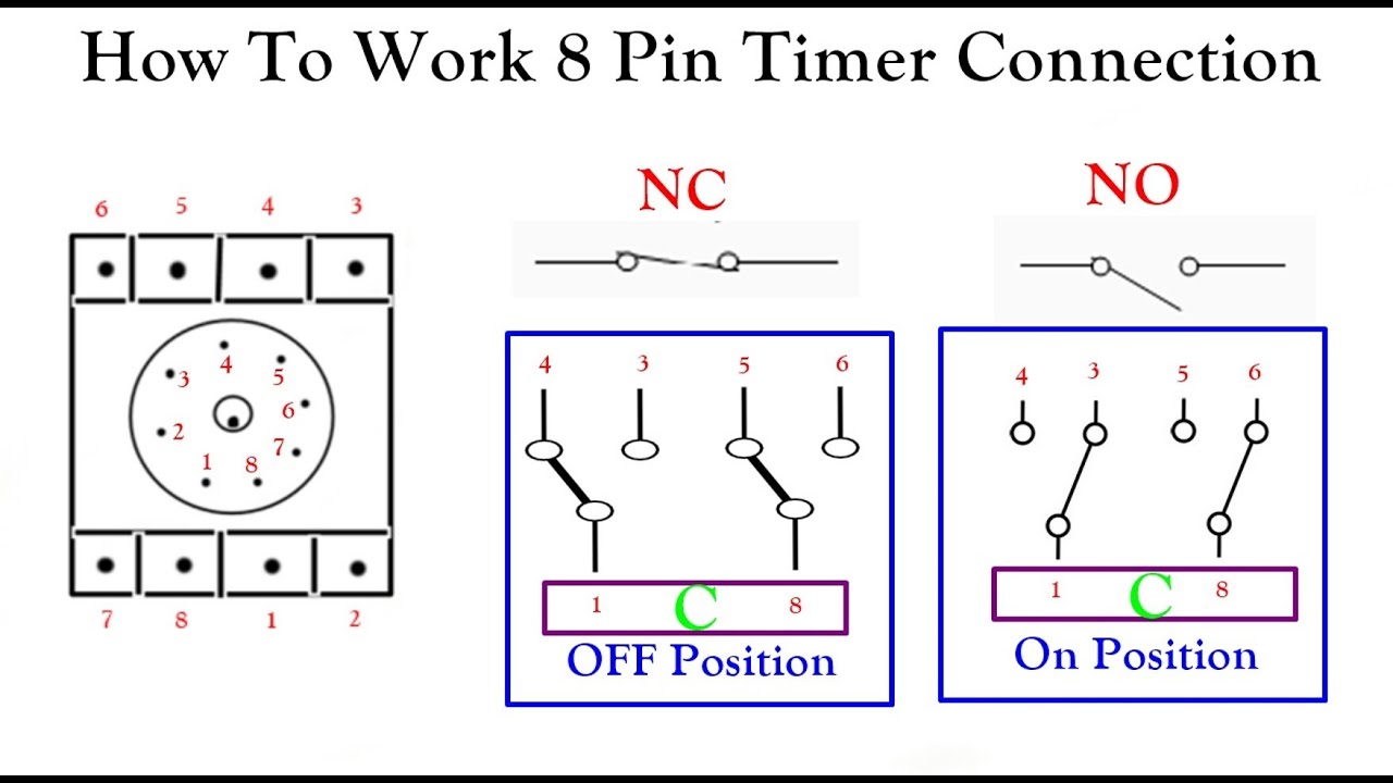
How to wire Pin timers
PDF DROK Timer Relay P3: Relay will turn ON for time OP after getting a trigger signal and then turn relay OFF.Module will reset and stop timing if it gets a trigger signal again during delay time OP. P4: Relay will turn OFF for time CL after getting a trigger sighal and then relay will turn ON for time OP.Relay will turn OFF after finish timing.

How to wire an ON Delay Relay Timer | Honda Shadow Forums
8 pin timer relay wiring diagram - electrical and ... Aug 23, 2021 · 8 pin timer relay wiring diagram The electric timer allows a light point to be turned on from one or more places in the room, and to leave this light point on for an adjustable period of time. The control points are pushbuttons with indicator lights (in order to be able to locate them in the event of extinction).

Time Delay Relay using 555 Timer IC
Finder Relay Wiring Diagram - Wiring Tech Wiring diagrams 1301 1312 and 1371 Type 1301 Step wiring diagram Red LED indication. Continuous relay ON Type 1312 Call reset relay Type 1301 Monostable wiring diagram Red LED indication. Pin On Relays And Contactors 1 2 pole relay range 40 31 1 pole 10 a 3 5 mm pin pitch 40 51 1 pole […]

Pin on Weighing indicator
Time Delay Relay Basics: Relay Circuit and Applications Oct 20, 2020 · Figure 4. Time Relay Wiring Schematics . Time Relay Wiring: 1) Control wiring: Consider it as a DC relay. 2) Work control: Although the control voltage is connected, whether it plays a control role is determined by the timer on the panel.

Time Delay Relay Basics: Relay Circuit and Applications
Finder Relay Wiring Diagram - easywiring 13 series electronic step relays wiring diagrams 13 81 and 13 91 type 13 81 3 wire connection red led indication. It reveals the components of the circuit as simplified shapes and also the power and signal connections in between the tools. Pin On Relay Wiring Panel . Ah3 Delay Timer And Relay Timer Relay Home Electrical Wiring

How to wire Pin timers
12 Volt Relay Wiring Diagram - Wiring Diagram In addition, Wiring Diagram provides you with time body by which the tasks are to be completed. You will be able to know precisely if the projects needs to be finished, which makes it much easier for you to effectively handle your time. Multiple 12V Relay Wiring Diagram | Wiring Diagram - 12 Volt Relay Wiring Diagram
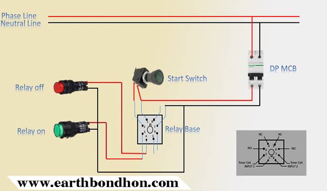
Timer Testing Wiring Diagram – Earth Bondhon
Contactor And Relay Wiring Diagram - The Wiring Single Pole Contactor Relay Wiring Diagram 240v Single pole means that it can only control a single circuit and single throw means that there are only two positions the switch can be in one on and one off state mechanical relays do not The esd5 series is an accurate solid state delayed interval timer it offers a 1a steady 10a inrush output and ...

8 pin timer relay wiring diagram
PDF Timing Diagrams Overview Timers - IDEC Corporation Relays Sockets Timers Contactors Terminal Blocks Circuit Breakers 800-262-IDEC (4332) t SA & Canada 833 Timers Timing Diagrams Overview Cycle 1 (power start, OFF first) When voltage is applied to the coil, the contacts remain in the off state and the set time begins. At the end of the set time, the contacts transfer to the on state

How to connect and set analog timer relay
Time Delay Relay TDR 120VAC 24VDC

Industrial Motor Control: Timing Relays

Analog Operation ATS wiring diagram | Download Scientific Diagram

12V Relay With Timer Switch : 4 Steps - Instructables

Buy Timer Relay DC 12V 24V Time Delay Relay Controller Board ...
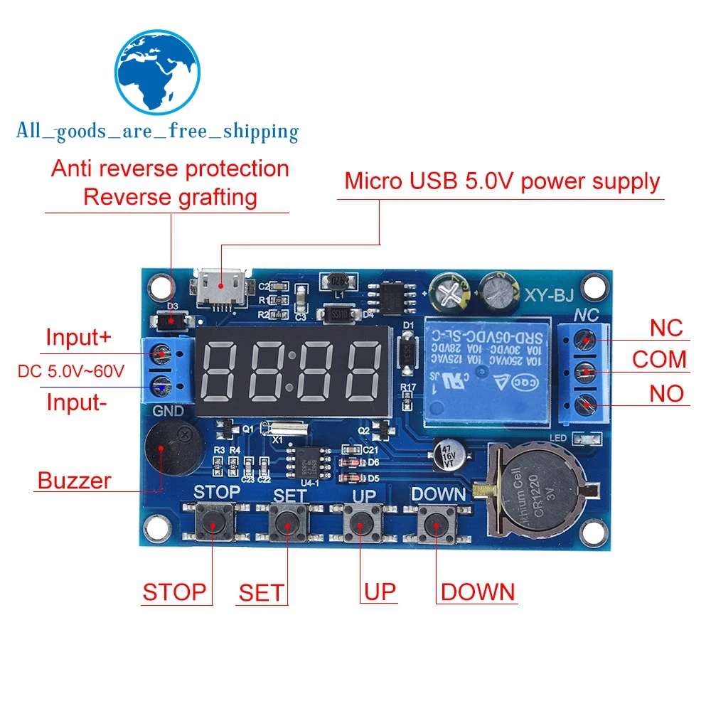
DC 5V Real time Timing Delay Timer Relay Module Switch Control Clock Synchronization Multiple mode control Wiring diagram

Timer Delay Relay, AC 110V 120V Programmable Digital Cycle ...
timer - How to wire this delay relay switch - Electrical ...
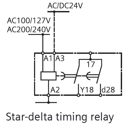
What is Star Delta Timer, Circuit Diagram, Working Siemens ...

How to wire Pin timers

NJB1-S Relay Datasheet pdf - Delay Relay. Equivalent, Catalog
Digital Timer Relay, 8 Pin, 12V/24V/220V | ATO.com

4541 Timer Relay Circuit 0.3 second to 10 hours

ST01 delay timer | Electrical circuit diagram, Timer, Basic ...

How to wire Pin timers
How To Use Timer Relay How To Connect 8 Pin Timer Connection Wiring Diagram

12V Relay With Timer Switch : 4 Steps - Instructables
Programmable Timer Relay, 8-Input 8-Output, 12V/24V DC | ATO.com
Digital Timer Relay, 8 Pin, 24V DC/110-240V AC | ATO.com

8 Pin Timer Wiring Diagram
8 Pin Timer Relay Wiring Diagram | Basic Timer Connection And Function |
0 Response to "37 timer relay wiring diagram"
Post a Comment