39 incineration process flow diagram
Solid Waste Management Process Flow Chart - ione.eu.org Flow chart of incineration process The collected material is located in a land site and from here taken to be sent to the incineration process normally performed in grid or rotating kilns. Federal State and Local governments along with private sector service. Processes involved in Solid Waste Management. PDF Chapter 2 - Incinerators and Oxidizers In this context, the terms "incineration" and "oxidation" refer to several different thermal treatments of organic substances in waste materials. The term incineration is generally used to describe a process for the combustion of solid and liquid wastes, such as hazardous, medical, municipal, or sewage waste.
Process flow diagram of inceration process unit | Download ... ... incineration process used moving grate incinerator (I -101) before followed by the cooling of the flue gas through superheated steam generation in E-101. The cool flue gas was cleaned in the...

Incineration process flow diagram
Spray drying - Wikipedia Spray drying is a method of producing a dry powder from a liquid or slurry by rapidly drying with a hot gas. This is the preferred method of drying of many thermally-sensitive materials such as foods and pharmaceuticals, or materials which may require extremely consistent, fine, particle size. Claus Process - an overview | ScienceDirect Topics Figure 9.10 shows a simplified flow diagram of a two-stage Claus process plant. The first stage of the process converts H 2 S to sulfur dioxide and to sulfur by burning the acid gas stream with air in the reaction furnace. This provides SO 2 for the next phase of the reaction. How it Works - The Incineration Process at the Metro Plant ... The Metro Plant has been processing wastewater solids with incineration since 1938 and with fluid bed incinerators since 2005. Incineration of wastewater soli...
Incineration process flow diagram. incineration flow diagram - northrichlandhillsdentistry That is special incineration flow diagram helps you searching by ingredients, nutrions and categories. Waste to Energy (Incineration) Wholesaler - PEAKS ECO WTE Incineration plant working flow diagram: This interactive graphic explains how the Waste to Energy plant works. It has been open since 2014 and operating at full capacity since day one. How Waste Incineration Works - Earth911 Waste-to-Energy. The waste management industry usually calls incineration "waste-to-energy," or WTE, to emphasize the energy recovery process that makes modern incinerators both a waste disposal and electric power generating utility. In most incinerators and all newly constructed ones, the heat released from burning waste is used to produce ... Incineration - SlideShare introduction of incineration process incineration is a waste treatment process that involves the combustion of organic substances contained in waste materials. incineration of waste materials converts the waste into ash, flue gas and heat. the ash is mostly formed by the inorganic constituents of the waste, and may take the form of solid lumps … incineration process - YouTube About Press Copyright Contact us Creators Advertise Developers Terms Privacy Policy & Safety How YouTube works Test new features Press Copyright Contact us Creators ...
Grate Type Incineration | Waste Treatment | Solution ... Process Flow Diagram Overview Our grate type incineration is equipped with a rotating furnace that efficiently mixes, stirs and incinerates waste. With the furnace walls consisting of boiler water tube walls, the facility also boasts a simple and solid structure with a relatively low number of moving parts. Features 1. Versatile Thermal Oxidation - an overview | ScienceDirect Topics Simplified flow diagrams of thermal incineration systems using recuperative and regenerative heat exchangers, respectively, are shown in Figures 13-1 and 13-2. Figure 13-1 . Simplified flow diagram of typical thermal oxidation system with recuperative heat recovery. Incineration Solid Waste Management - Seminars Topics Different versions of the hierarchy exist but in most of the cases the following order suggests: 1. Reduce the quantity of waste 2. Reuse 3. Recycle the materials 4. Incinerate with heat recovery 5. Landfill of inert ash The first priority, to reduce the quantity or volume of waste, which is generally accepted. Fume Incinerator System Process Design Package Preparation The process design project included completion of the following tasks: Process design basis development, including vent stream characterizations. Regulatory design basis development, including required control system removal efficiencies. Process design, and process flow diagram (PFD) and process description preparation.
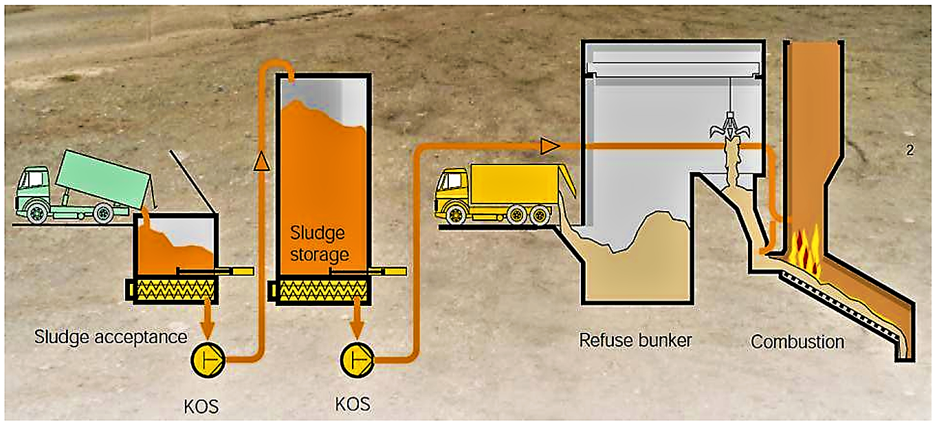
Incineration Process - an overview | ScienceDirect Topics The main stages of a typical sewage sludge incineration process are shown in Figure 3.6 and can be divided into four main parts: sludge pretreatment, combustion, energy recovery and cleaning systems. Relevant literature on this process is cited in Figure 3.6 for further reference for the reader. Sign in to download full-size image Figure 3.6. Flue-gas stack - Wikipedia Flue-gas flow-rate induced by the draft. As a "first guess" approximation, the following equation can be used to estimate the flue-gas flow-rate induced by the draft of a flue-gas stack. The equation assumes that the molar mass of the flue gas and the outside air are equal and that the frictional resistance and heat losses are negligible:. Utility systems - processdesign Feb 22, 2016 · Gas-Turbine Cogeneration Process. When generating energy on-site, many plants use a gas-turbine cogeneration process. The thermal efficiency of a gas-turbine process is in the range of 70-80% while conventional power stations, such as coal-fired processes, have a 30-40% efficiency. PDF 2.3 Medical Waste Incineration 2.3.1 Process Description1-6 Types of incineration described in this section include: - Controlled air, - Excess air, and - Rotary kiln. 2.3.1.1 Controlled-Air Incinerators - Controlled-air incineration is the most widely used medical waste incinerator (MWI) technology,
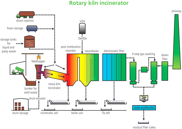
Process scheme of the rotary kiln for hazardous waste ...
Incineration - an overview | ScienceDirect Topics General schematic diagram of the incineration process [29]. For optimum efficiency, any incinerator should be focused on the "Three T's." The Three T's stand for "time," "temperature," and "turbulence." These Three T's play very important roles in determining the efficiency of an incinerator.
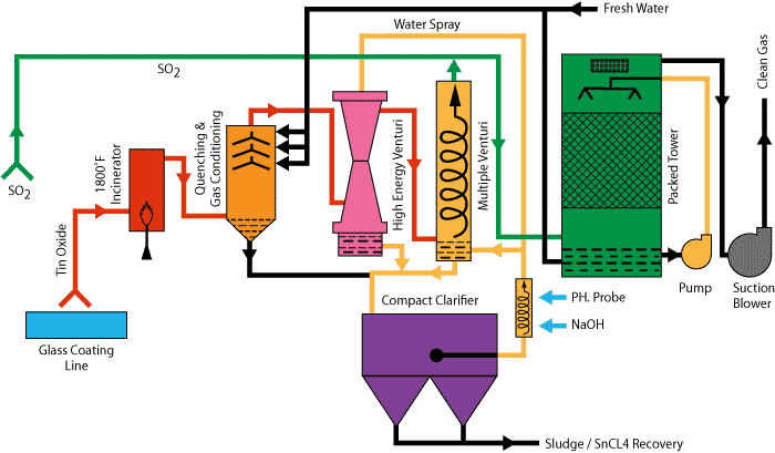
Multi-Stage Scrubbing Systems - Monroe Environmental
Practical Fundamentals of Chemical Engineering - EIT ... The flow rate of a process stream may be expressed as a mass flow rate (mass/time) or as a volumetric flow rate (volume/time). Consider a fluid (gas or liquid) which flows in a cylindrical pipe as shown in Figure 2.5, where the shaded area represents a section perpendicular to the direction of flow.
Waste Treatment With Incinerator - PPLI
Process Flow Diagram - Feedstock Recycling - Benefits of ... Process Flow Diagram. In this section we discuss the process flow diagram for the pyrolysis of waste plastics. This is required to be a compact process that can be controlled in a stable and continuous way, because of movement of the high-viscosity material for each unit system in the process. This material can block the flow line and make ...

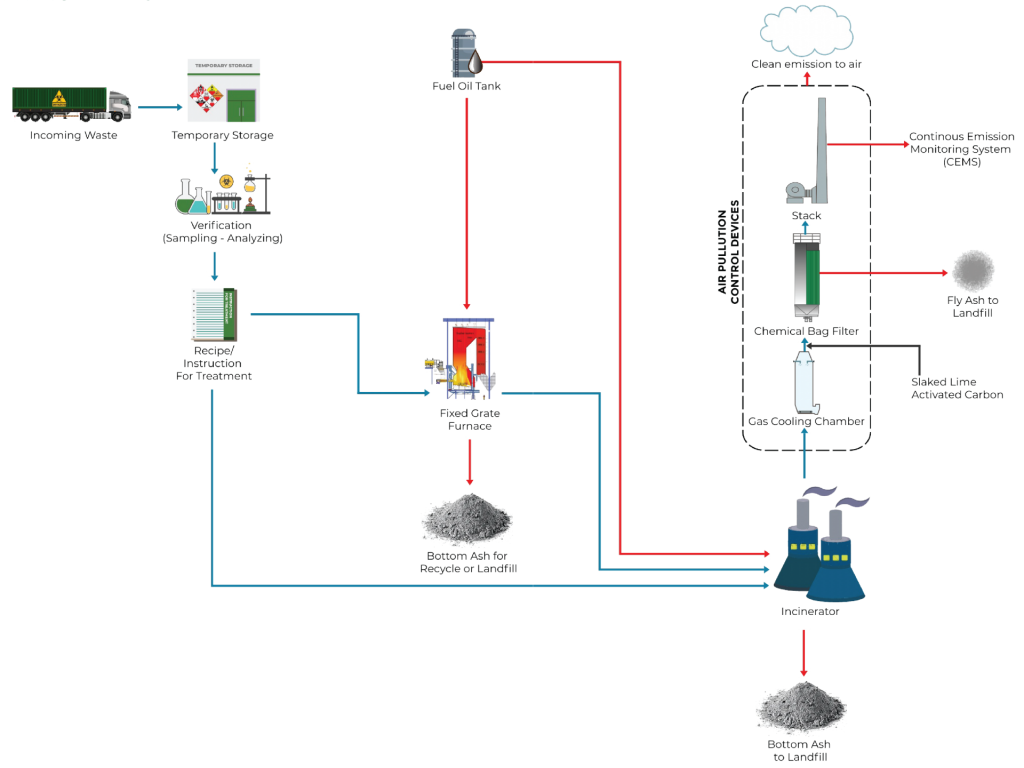
Using a State-of-the-art Air Pollution Control System to ...
Incinerator Process Flow | Heritage® The gas streams into this unit, where it is cooled with sprays of water. This cooling process generates salt, which is collected at the bottom of the cone. Like the slag, it is sent offsite to an authorized hazardous waste landfill for disposal. In addition to cooling the gas, the spray dryer completely evaporates water from the wet scrubber [6].

An Independent Engineering Evaluation of Waste-to-Energy ...
CDC - Chemical Weapons Elimination - Incineration Incineration. Incineration is the most common method of chemical agent destruction. It was selected in the early 1980s by the Department of Defense as the preferred method for disposal of chemical agents and munitions after long and careful consideration of several technologies. The National Research Council endorsed this selection in 1984 and ...

INCINERATION PLANT WITH DOWNFLOW
Waste to Energy (Incineration) Wholesaler - PEAKS ECO WTE Incineration plant working flow diagram: This interactive graphic explains how the Waste to Energy plant works. It has been open since 2014 and operating at full capacity since day one. We also consistently operate within all pollution limits and report on the plant's emissions on a monthly basis here. Introdction of incineration plant:
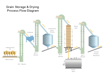
Grain Storage and Drying Process Flow Diagram | EdrawMax ...
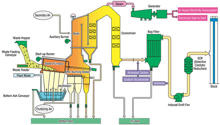
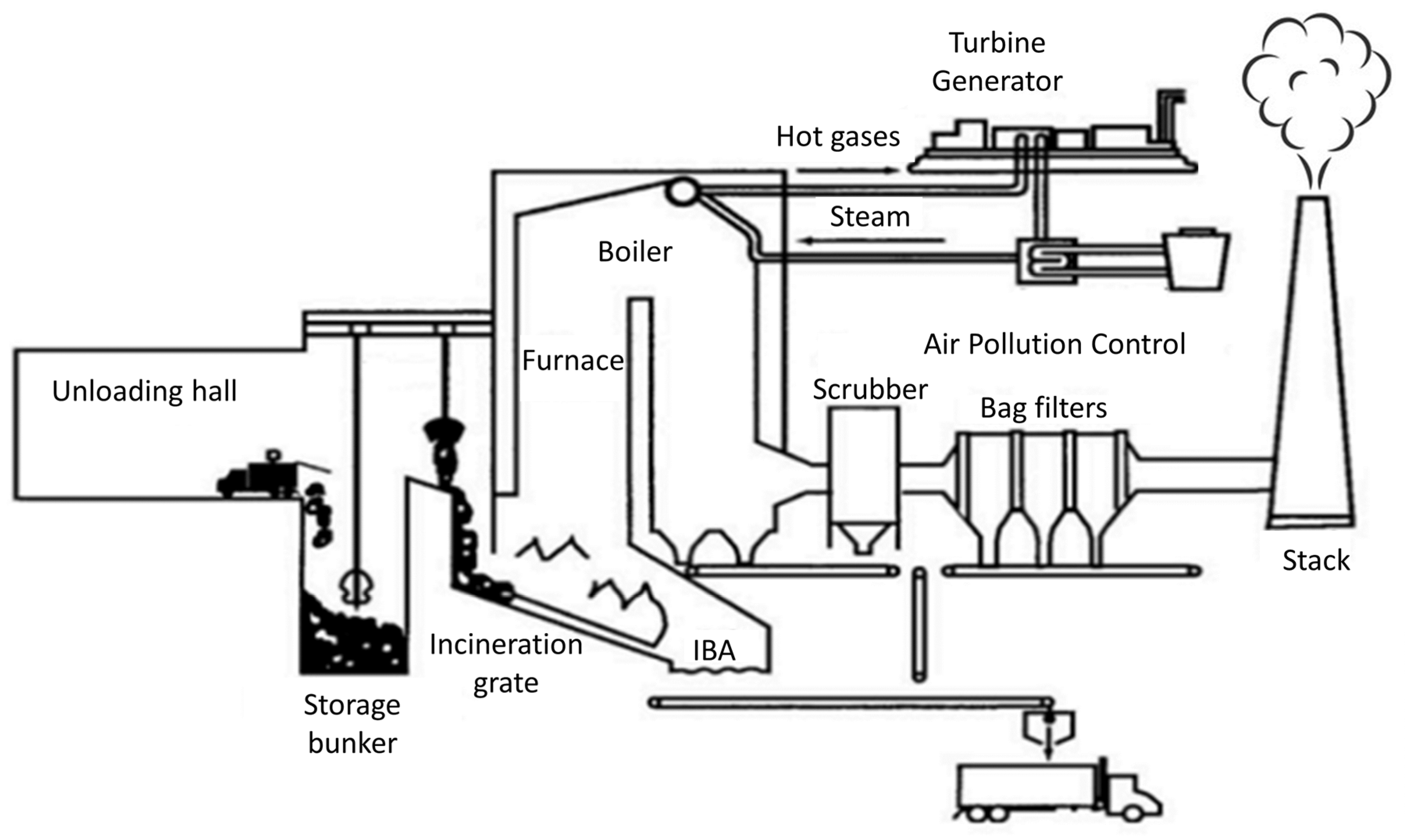
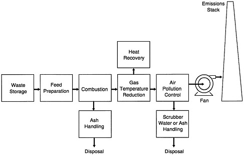
PDF Incineration With Energy Recovery Incineration Process flow diagram Grabber collects waste Ash and materials Steam Generator Chimney Scrubber Particulate removal system Incinerator Electricity Technology overview Incineration (i.e. mass burn) is one of the most common forms of thermal waste treatment technology.
Incineration biomedicalwaste
Process Description of Process Flow Diagram - [DOC Document] Process description of process flow diagram (PFD)Raw Material Storage Chlorine, oxygen and ethylene are fed as gases into the respective reactors. These feed gases are stored in spherical tanks under pressure. Chlorine is stored in T01, Ethylene in T02 and Oxygen in T03. It is from these storage tanks that t he feed gases are pumped to the ...
Incineration (Large-scale) | SSWM - Find tools for ...
Incineration—process flow diagram | Download Scientific ... Incineration of solid wastes is reported to show a higher volume reduction of greater than 90% [23, 98,99]. Furthermore, a twofold benefit could be observed as a result of incineration of mixed...

1 December 8, Clean Harbors Company Confidential A Brief ...
Process Flow Diagram Pdf - super menu master library ... Here are a number of highest rated Process Flow Diagram Pdf pictures upon internet. We identified it from well-behaved source. Its submitted by executive in the best field. We say yes this kind of Process Flow Diagram Pdf graphic could possibly be the most trending subject taking into account we portion it in google plus or facebook.

SEE Information Portal - Technologies - Waste
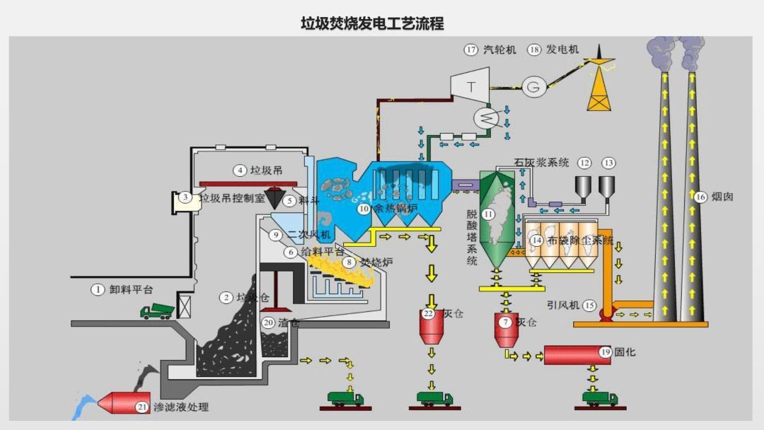
PDF Incineration Process for Solid Waste Management and ... Flow chart of incineration process The collected material is located in a land site and from here taken to be sent to the incineration process, normally performed in grid or rotating kilns. The gas coming from the combustion process at a temperature around 900o C to 1000o C is sent to a heat exchanger for steam production to
EFFICIENCY IMPROVEMENTS IN WASTE-TO-ENERGY COMBUSTION ...
Municipal Solid Waste Incinerator Design: Basic Principles Typical grate firing systems for refuse incineration are shown in Figure 1: (i). Reciprocating grates, (ii). Roller grates and, (iii). Reversed feed grates. Depending on the grate type, the furnace geometry and the secondary air injection concept have to be optimized. Typically, the primary combustion air cools the grate bars.
Grate Type Incineration | Waste Treatment | Solution ...
5.2. Recycling: open-loop versus closed-loop thinking | EME ... The diagram in Figure 5.1. shows a material flow through the linear (open-loop) system. In this representation, stocks are shown with rectangular boxes, and transforming processes are shown by hexagon boxes. In Figure 5.1. below, we see that natural resources extracted from the environment are transformed into a product via manufacturing process.
Fluidized Bed Incinerator for Municipal Waste
explain the process of incineration with the diagram ... Incineration is a method in which waste is burnt at very high temperatures. Hazardous bio-medical wastes such as discarded medicines, toxic drugs, human anatomical wastes, blood, pus, microbiological and biotechnological wastes, etc. are usually disposed off by incineration. Purpose of incineration: Reduces the volume of waste

Explain with a neat sketch the working of municipal incinerator.
(Pdf) Incineration Process for Solid Waste Management and ... Incineration is the best process of combustion of Organic materials present in the waste and giving useful A typical scheme for an incineration plant operating on real byproducts. The by-products of incineration are heat, flue waste and with energy recovery is given in Fig. 1 gases and ash.
Applied Sciences | Free Full-Text | Opportunities and ...
schematic flow diagram of a rotary kiln incinerator process flow diagram calcined coke « Mining 2013-6-14 Vertical Calcined Petroleum Coke Incinerator - Patent application. 24 May 2012 During the calcination process of green petroleum coke, volatile matter from the kiln, in the direction of gas flow, in a horizontal incinerator.

Flow diagram of the waste incinerator that uses Thiourea (1 ...
Problems & Solutions - Environmental Protection Department To ensure that the gas emissions meet the stringent standards imposed by regulatory bodies (e.g. EU Waste Incineration Directive) for public health and environmental protection, modern incineration plants adopt a number of advanced design and process controls as well as exhaust gas cleaning measures as illustrated by the flow chart below:

Sewage Sludge Ash - Material Description
How it Works - The Incineration Process at the Metro Plant ... The Metro Plant has been processing wastewater solids with incineration since 1938 and with fluid bed incinerators since 2005. Incineration of wastewater soli...
ENERGY FROM WASTE: REVIEW OF THERMOCHEMICAL TECHNOLOGIES FOR ...
Claus Process - an overview | ScienceDirect Topics Figure 9.10 shows a simplified flow diagram of a two-stage Claus process plant. The first stage of the process converts H 2 S to sulfur dioxide and to sulfur by burning the acid gas stream with air in the reaction furnace. This provides SO 2 for the next phase of the reaction.
INCINERATION PROCESS FOR SOLID WASTE MANAGEMENT AND EFFECTIVE ...
Spray drying - Wikipedia Spray drying is a method of producing a dry powder from a liquid or slurry by rapidly drying with a hot gas. This is the preferred method of drying of many thermally-sensitive materials such as foods and pharmaceuticals, or materials which may require extremely consistent, fine, particle size.
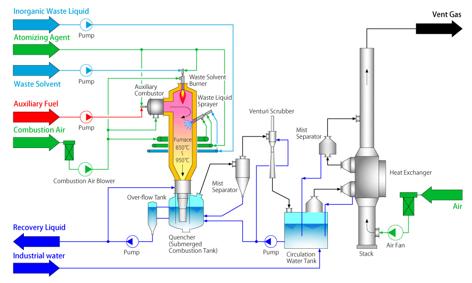
Incinerator for Waste Liquid & Gas | Environmental Plant ...
Garbage in, garbage out: Incinerating trash is not an ...

500t/D Municipal Solid Hazardous Waste Incineration to Energy ...
.jpg)
What is Incineration?

Description of Flow Diagram - Bali Refuse Incineration Plant
INCINERATION PROCESS FOR SOLID WASTE MANAGEMENT AND EFFECTIVE ...

Incinerator Process Flow | Heritage®
Incineration of Hazardous Waste: A Sustainable Process ...

Furnace Incineration Municipal solid waste 清掃工場 Boiler ...

China Vertical Rotary Pyrolysis and Gasification Incineration ...

SEE Information Portal - Technologies - Waste

Process flowchart of the MSW incineration unit. | Download ...
Evaluating the Waste Incineration Process for Sustainable ...

Medical waste incinerator(mid-size) | KRICO
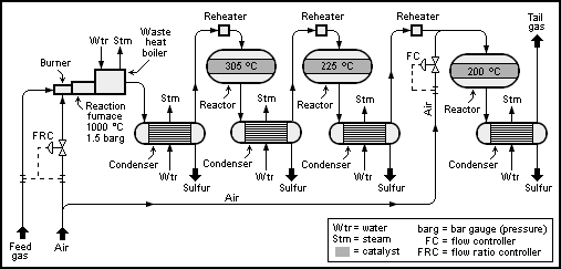
Claus process - Wikipedia

Incineration Process - an overview | ScienceDirect Topics
Typical process flow diagram of waste to energy Incineration ...
技术支持-Global solution provider for converting waste into ...
Incineration Processes and Environmental Releases | Waste ...
0 Response to "39 incineration process flow diagram"
Post a Comment