39 fe si phase diagram
PDF The Al-Si Phase Diagram - Buehler, an ITW Company For alloys with a low Si con tent, the Fe is present as Al3Fe while at higher Si levels, first α-Al12Fe3Si (cubic crystal structure) and at still higher Si levels β-Al9Fe2Si (monoclinic crystal structure) will form. isit our esite at uehlercom for more information The Al-Si Phase Diagram Fe-Si Phase Diagram - Phase diagram of the Fe-Si system ... Fe-Si Phase Diagram - Phase diagram of the Fe-Si system - SpringerMaterials MSI Eureka Phase diagram of the Fe-Si system Figure 2 from evaluation report: C-Fe-Si Ternary Phase Diagram Evaluation Phase diagram available to subscribers If you are having trouble in accessing SpringerMaterials remotely during the COVID-19 pandemic,
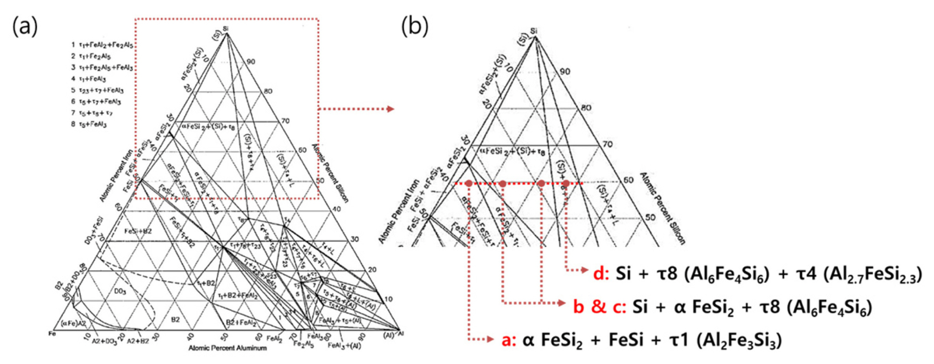
Portion of Fe-Al-Si Phase diagram calculated by Thermo ... The solidified Al-Si coating layer consisted of three phases of Al, Si, and τ5 (Al8Fe2Si). The reaction layer on the Al-Si coating layer side is a fine τ5 phase (Al8Fe2Si) of 5 μm thickness.

Fe si phase diagram
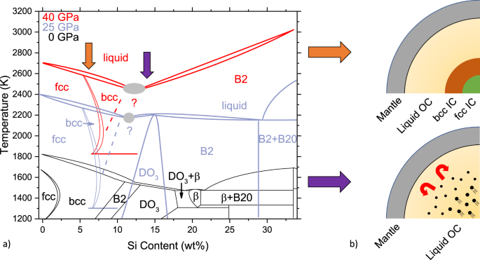
Assessment of the ternary Fe-Si-B phase diagram ... The aim of this initial optimization procedure is to obtain the stable ternary phase diagram which results comparable to that obtained by Tokunaga as shown in the isothermal section at 1000 °C ( Fig. 4 ); we just find a smaller two phase Fe 2 Si 0.4 .B 0.6 -bcc region with respect to [1]. Fe-Ge-Si (Iron-Germanium-Silicon) - Journal of Phase ... T. Kozakai and T. Miyazaki: "Experimental and Theoretical Phase Diagrams of the Iron-Rich Fe-Si-Ge Ordering System," J. Mater. Sci., 1995, 30, pp. 5056-64. Article ADS Google Scholar Download references The Fe-FeSi phase diagram at Mercury's core conditions ... Both scenarios are found either in the Fe-Si phase diagram at ambient pressure 49, or related iron-based alloys, e.g., Fe-V, 35. At higher pressures, the hcp + B2 region expands in temperature to...
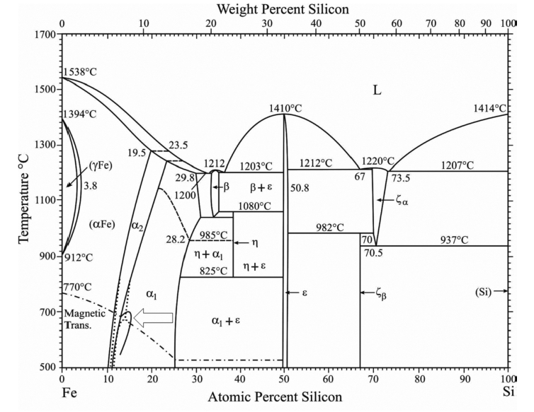
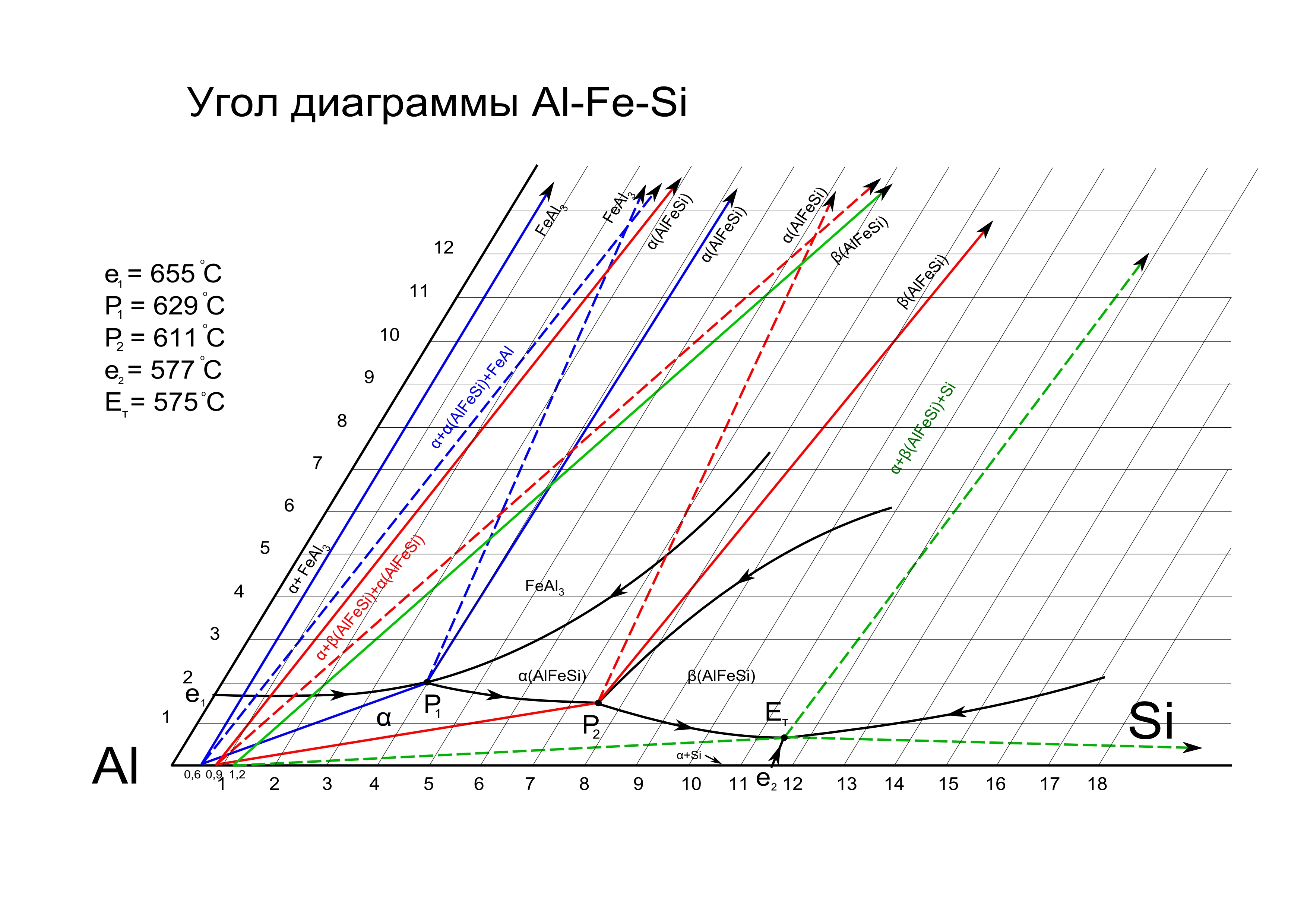
Fe si phase diagram. Phase equilibria and structural investigations in the ... Our experimental results are generally in good agreement with the most recent phase diagram versions of the system Al-Fe-Si. A new ternary high-temperature phase τ12 ( cF 96, NiTi 2 -type) with the composition Al 48 Fe 36 Si 16 was discovered and was structurally characterized by means of single-crystal and powder XRD. PDF Chapter 2 Alloys of the Al-Mg-Si-Fe System Phase diagram of Al-Fe-Mg system: (a) liquidus and (b) solidus. which becomes 14.1% Mg at 449°C as compared with 17.45 in the binary Al-Mg system. Nonequilibrium solidification facilitates the formation of the degenerated ternary eutectics with large AlaFe particles formed at low Fe concentration and with AlgMgs compound appearing even at 2-3% Mg. The Fe-Si phase diagram: from electrical steel to the ... The standard phase diagram for Fe-Si is the one by Kubaschewski (1982). In the iron-rich region, the dominant phases are a-Fe (0 at.% Si), DO3 (a1, 25 at.% Si) and B20 (e, 50 at.% Si). a and a1 have the bcc lattice as underlying lattice, and a1 consists of an ordered replacement of one quarter of the Fe atoms by Si. PDF Chapter 1 Alloys of the Al-Fe-Mn-Si System The AlsFeSi phase (25.6% Fe, 12.8% Si), also designated as Al9Fe2Si2 and P(AlFeSi), exists in a homogeneity range of 25-30% Fe, 12-15% Si. This phase has a monoclinic crystal structure with parameters fl = Z7 = 0.612nm, c = 4.148-4.150nm, P = 91°. It has a density of 3.3-3.6 g/cm^ and a Vickers hardness of 5.8 GPa (Belov et al., 2002a).
On the Phase Diagrams of the Al-Fe and Al-Fe-Si Systems ... On the Phase Diagrams of the Al-Fe and Al-Fe-Si Systems p.331. Recrystallization in Supersaturated Al-Fe, Al-Si and Al-Fe-Si Alloys: A Differential Scanning Calorimetry Study p.337. Effect of Heat Treatment on the Microstructure of Cast Al-Fe-Si Alloys p.343. The Microstructure of Al-Fe-Si, Al-Fe-Mn-Si and Al-Fe-Mn-Mg-Si Rolling Ingots in ... PDF Phase Diagrams of Fe-Si Alloys under High Pressures Phase Diagrams of Fe-Si Alloys under High Pressures J. F. Lin,1D.L. Heinz,1,2A. J. Campbell,1J. M. Devine1 1Department of the Geophysical Sciences and 2James Franck Institute, The University of Chicago, Chicago, IL, U.S.A. Introduction Iron is the most abundant element in the Earth's core. Phase diagram of the Fe-S-Si system in this study. Open ... To better understand the solidification and element partition processes and to build a plausible geodynamic model for the ICB, we investigated the P-T phase diagram of Fe-Si-O system from 313 to... PDF The iron-iron carbide (Fe-Fe3C) phase diagram Si Mn W Mo Review Fe-C phase diagram • 2 important points-Eutectoid (B): γ⇒α+Fe 3C-Eutectic (A): L ⇒γ+Fe 3C Fe 3 C (cementite) 1600 1400 1200 1000 800 600 400 0 12 3 4 5 66.7 L γ (austenite) γ+L γ+Fe 3C α+Fe 3C α + γ L+Fe 3C δ (Fe) C o, wt% C 1148°C T(°C) α 727°C = Teutectoid A R S 4.30 Result: Pearlite = alternating layers ...
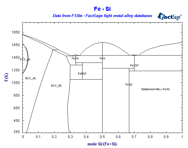
(PDF) Fe-Ni-Si (Iron-Nickel-Silicon) | Vijayaraghavan ... Part 1: Phase Diagrams for Binary Fig. 1. The previously known ternary phase of nominal and Ternary Alloys of Fe-Cr and Ni with C and with Si, Rep. formula Fe5Ni3Si2 (denoted s here) is present with a EUR 9657/I/EN, Comm. Eur. Communities, 1985, p 1-135 homogeneity range of 46.5-56.3 at.% Fe-Si - Phase Diagram - Google Search Phase Diagram. このサイトを検索 ... Fe-Si. Data from RICT-Sol alloy database ver.1.0. Sign in | Recent Site Activity | Report Abuse | Print Page | Powered By Google Sites ... Phase diagram of URu 2- x Fe x Si 2 in high magnetic fields Electrical transport measurements were performed on URu 2 - x Fe x Si 2 single-crystal specimens in high magnetic fields up to 45 T (DC fields) and 60 T (pulsed fields). We observed a systematic evolution of the critical fields for both the hidden-order (HO) and large-moment antiferromagnetic (LMAFM) phases and established the 3D phase diagram of T-H-x In the HO phase, H/H 0 scales with T/T 0 ... Fe-Si Phase Diagram and Database (GeDb for FactSage) Fe-Si Phase Diagram [2014Yua] The re-assessment of the Mg-Zn and Fe-Si systems and their incorporation in thermodynamic descriptions of the Al-Mg-Zn and Fe-Si-Zn systems, Y.Yuan, F.Pan, D.Li, A.Watson, CALPHAD, 44(2014)54-61. Database for FactSage (registration required)
Binary Phase Diagrams
Phase Diagram - Google Search 計算熱力学はいわば"物性推算法"の一つであり、用いる熱力学データベースも、もっとも良さそうな"推算値"で構成されています。. これらは様々な情報に基づき、細心の注意を払って推定されたものですが、間違いや問題はあり得ます。. 従って、それ ...

Fe-Si - Phase Diagram
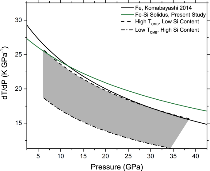
The FeSi phase diagram to 150 GPa - AGU Journals subsolidus phase diagram of FeSi are directly relevant to the CMB region. Second, the high‐pressure phase diagram of FeSi will help to constrain the topology of the Fe‐rich portion of the Fe‐Si system, which is important in deter- mining the distribution of Si within the core and lower mantle at the present day and during core formation
![PDF] Assessment of the ternary Fe–Si–B phase diagram ...](https://d3i71xaburhd42.cloudfront.net/6d7e78e3f8f05fa511ab11788407d75a18da9b0b/14-Figure3-1.png)
PDF] Assessment of the ternary Fe–Si–B phase diagram ...
Ferro-Manganese - IspatGuru deoxidizer, Fe-Mn, Fe-Si, HC Fe-Mn, hot shortness, LC Fe-Mn, MC Fe-Mn, phase diagram, Si-Mn, Ferro-Manganese. Ferro-manganese (Fe-Mn) is a metallic ferro alloy which is added usually along with ferro-silicon (Fe-Si) as ladle addition during steelmaking. It is a ferroalloy composed principally of manganese (Mn) and iron (Fe), and normally ...
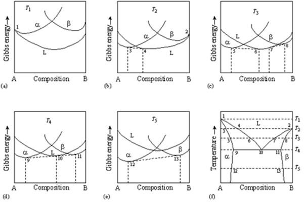
Teach Yourself Phase Diagrams and Phase Transformations
PDF PHASE RELATIONS OF Mn-Fe-Si-CSYSTEMS Phase relations ofMn-Fe-Si-Csystems are established by means ofreported binary diagrams, and calculations of ternary and quaternary diagrams. The phase relations are presented in diagrams for six binary and four higher order systems, the latter as liquidus surfaces and solid state equilibria at fixed temperature.
![Binary phase diagram of the Fe-Si system [31] | Download ...](https://www.researchgate.net/profile/Farah-Liana-Mohd-Redzuan/publication/333432142/figure/fig1/AS:910542218727424@1594101590354/Binary-phase-diagram-of-the-Fe-Si-system-31.png)
Binary phase diagram of the Fe-Si system [31] | Download ...
DIAGRAM OF EQUILIBRIUM PHASE COMPOSITION OF Fe - C - Si ... The studied four-component Fe - C - Si - B system in graphic representation this diagram represents a tet- rahedron including one -, two - and three - component private systems. In Table 1 there is shown the list of all private sys- tems. The construction of a diagram of the phase composi- tion of the four - component Fe - C - Si - B system
Thermodynamic modeling of Al–Fe–V ternary system
Fe-Si-Sn Isothermal Section of Ternary Phase Diagram ... Phase diagram available to subscribers; If you are having trouble in accessing SpringerMaterials remotely during the COVID-19 pandemic, ... Fe-Fe 90 Si 10-Fe 87 Si 10 Sn 3-Fe 92 Sn 8; Apdic: non-APDIC Investigation Type: experimental, detailed ...
The Fe-Si phase diagram: from electrical steel to the planet ...
THERMODYNAMIC MODELING OF PHASE COMPOSITION FOR Fe-Ca-Si ... carried out to plot the phase structure diagram of the Fe-Ca-Si-Al system as a modeling composition of the final alloy by the method of thermodynamic diagram analysis (TDA). TDA allows obtaining data for the system in the form of a phase diagram, each elementary subsystem in this diagram is independent. Subsystem can be regarded as a quasi-system.
Solidification of steels
All Phase Diagrams - Polytechnique Montréal FactSage 8.1 - List of Stored Phase Diagrams (7811) FACT Databases. FToxid FACT oxide data (501) FTsalt salt data (351) FTmisc sulfide, alloy, micellaneous data (39) ... Ag-Fe-Si_1550C SGnobl: Ag-Ga FScopp: Ag-Ga FSlead: Ag-Ga FTlite: Ag-Ga SGTE 2020: Ag-Gd SGTE 2020: Ag-Ge BINS: Ag-Ge FScopp: Ag-Ge FTlite: Ag-Ge SGnobl: Ag-Ge SGTE 2014: Ag-Ge ...
The C-Fe (carbon-iron) system
Computer calculations of metastable and stable Fe-C-Si ... Computer calculations of metastable and stable Fe-C-Si phase diagrams from binary thermodynamic properties Computer calculations of metastable and stable Fe-C-Si phase diagrams from binary thermodynamic properties. Download File. r_8627100.pdf (1004.34 KB) Date. 1986. Authors. Chueh, Shan-Chang. Journal Title. Journal ISSN.

Melting experiments on Fe–Si–S alloys to core pressures ...
Fe—Si Iron—Silicon | SpringerLink A set of interdependent thermodynamic values, consistent with the Fe-Si phase diagram, based on a critical assessment of all the published phase diagram and thermodynamic data has recently been submitted by Chart [1].
Fe (Iron) Binary Alloy Phase Diagrams
The Fe-FeSi phase diagram at Mercury's core conditions ... Both scenarios are found either in the Fe-Si phase diagram at ambient pressure 49, or related iron-based alloys, e.g., Fe-V, 35. At higher pressures, the hcp + B2 region expands in temperature to...
The Fe-FeSi phase diagram at Mercury's core conditions ...
Fe-Ge-Si (Iron-Germanium-Silicon) - Journal of Phase ... T. Kozakai and T. Miyazaki: "Experimental and Theoretical Phase Diagrams of the Iron-Rich Fe-Si-Ge Ordering System," J. Mater. Sci., 1995, 30, pp. 5056-64. Article ADS Google Scholar Download references
Thermodynamic assessment of the aluminum corner of the Al-Fe ...
Assessment of the ternary Fe-Si-B phase diagram ... The aim of this initial optimization procedure is to obtain the stable ternary phase diagram which results comparable to that obtained by Tokunaga as shown in the isothermal section at 1000 °C ( Fig. 4 ); we just find a smaller two phase Fe 2 Si 0.4 .B 0.6 -bcc region with respect to [1].
Thermodynamic assessment of the Al-Fe-Si system
ASM Phase Diagrams

Acta Metall Sin
PHASE RELATIONS OF Mn-Fe-Si-C SYSTEMS
The Fe-FeSi phase diagram at Mercury's core conditions ...
Perple_X vs THERMOCALC and/or Thermo-Calc
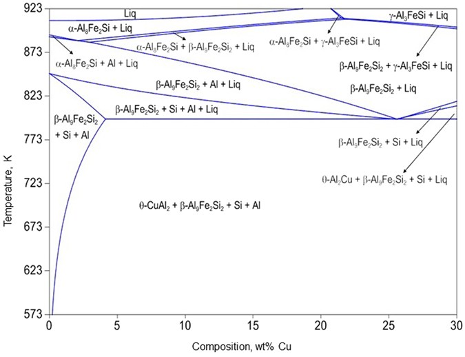
Influence of Cu on modifying the beta phase and enhancing the ...

Characterization of the Fe-rich corner of Al-Fe-Si-Ti ...

Segregation of P in Sub-Rapid Solidified Steels | IntechOpen

The FeSi phase diagram to 150 GPa - Lord - 2010 - Journal of ...
Al-rich Fe-Al based alloys : phase equilibria ...

PDF) Fe-Ni-Si (Iron-Nickel-Silicon) | Vijayaraghavan ...
Investigation on the 773 K isothermal section of Dy–Ni–Si ...
File:Al-Fe-Si 1.jpg - Wikimedia Commons

Fe-Si phase diagram: the γ loop. For Si concentrations ...
Fundamental Approach to Capacity Prediction of Si-Alloys as ...

Evidence for Fe-Si-O liquid immiscibility at deep Earth ...

Characterization of the evaluation of the solid solubility of ...
Formation of intermetallic phases in Al-10Si-0.3Fe based alloys
Sigma-phase in Fe-Cr and Fe-V alloy systems and its physical ...
INTERFACES BETWEEN SiC AND METALS

The FeSi phase diagram to 150 GPa - Lord - 2010 - Journal of ...
Collection of Phase Diagrams

Multicomponent Phase Diagrams: Applications for Commercial Aluminum Alloys

Electrochemical and Phase Analysis of Si(IV) on Fe Electrode ...
Thermodynamic and kinetic analysis of the melt spinning ...
0 Response to "39 fe si phase diagram"
Post a Comment