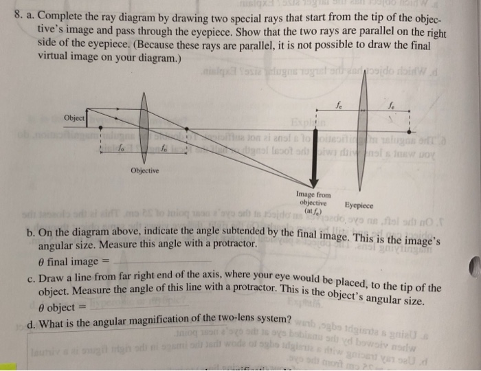
37 draw a ray diagram of the lens system in part d
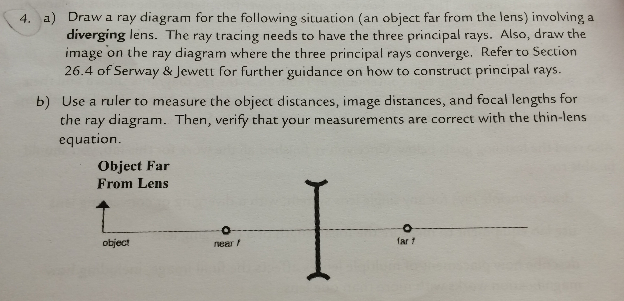
Advanced Physics questions and answers. 10. Draw a ray diagram for Method I. Use at least two rays. (8 pts) 11. Draw a ray diagram for Method II. Use at least two rays. (8 pts) Part 2: Diverging Lens to determine the focal length of a diverging lens, the ens must create a measurable, real image as in Part 1.. Convergin nh.
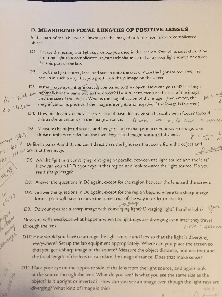
a) Draw a ray diagram of the experiment conducted in part C (determining your blinds spot) only include rays that travel straight from the laser on the board to your eye b) Draw a ray diagram of the lens system in part D; Question: Please help! I am not good a drawing ray diagrams, and I would like to double check what I did to make sure its right.
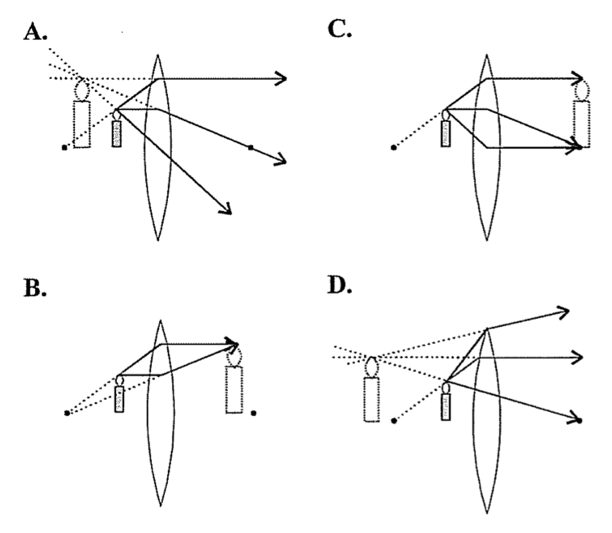
Part D . Converging Lens Example. In order to illustrate the method of drawing a ray diagram for a converging lens, we will consider the situation in which a real object is placed to the left of a converging lens. The bottom of the object will sit on the optical axis, and the top of the object will sit above the optical axis. ...

Draw a ray diagram of the lens system in part d
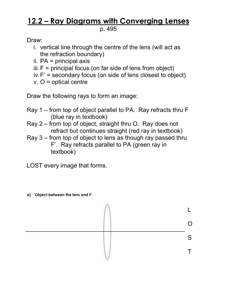
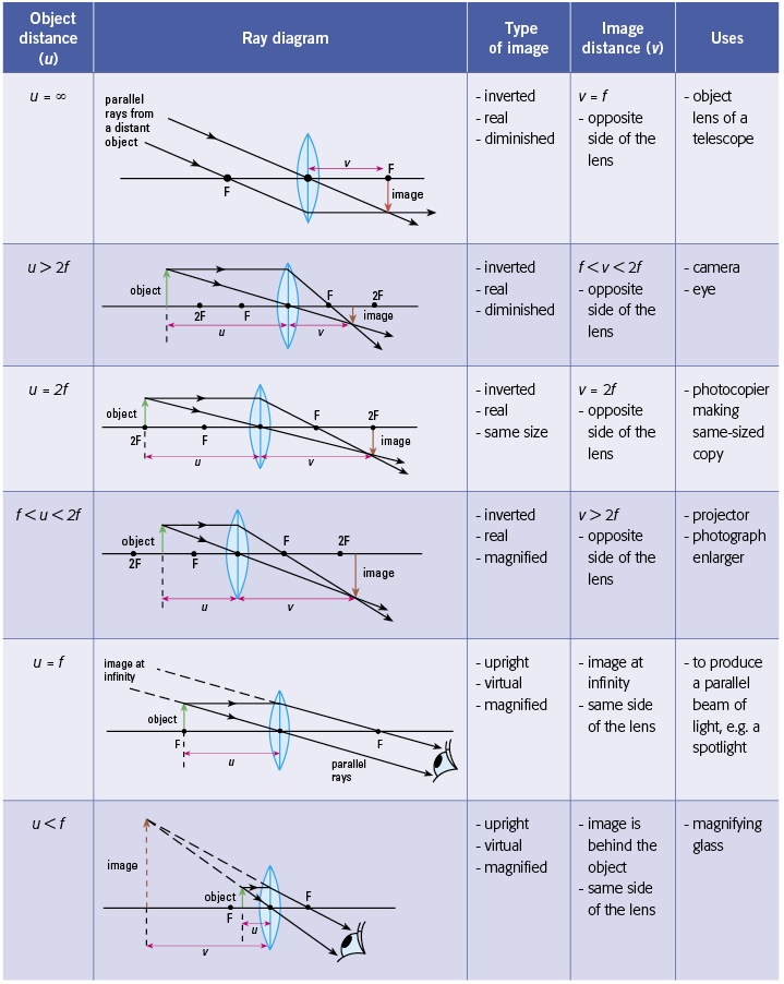
Step-by-Step Method for Drawing Ray Diagrams. The method of drawing ray diagrams for double convex lens is described below. The description is applied to the task of drawing a ray diagram for an object located beyond the 2F point of a double convex lens. 1. Pick a point on the top of the object and draw three incident rays traveling towards the ...
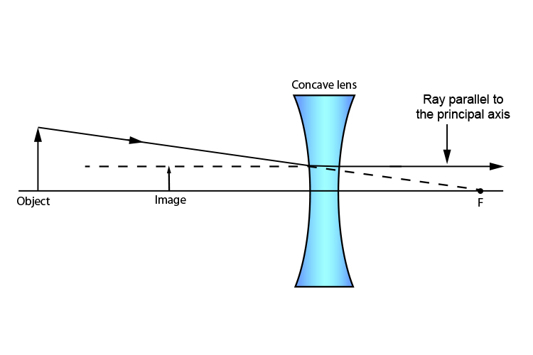
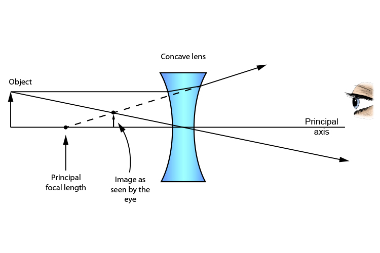
Ray Diagrams for Lenses. The image formed by a single lens can be located and sized with three principal rays. Examples are given for converging and diverging lenses and for the cases where the object is inside and outside the principal focal length.
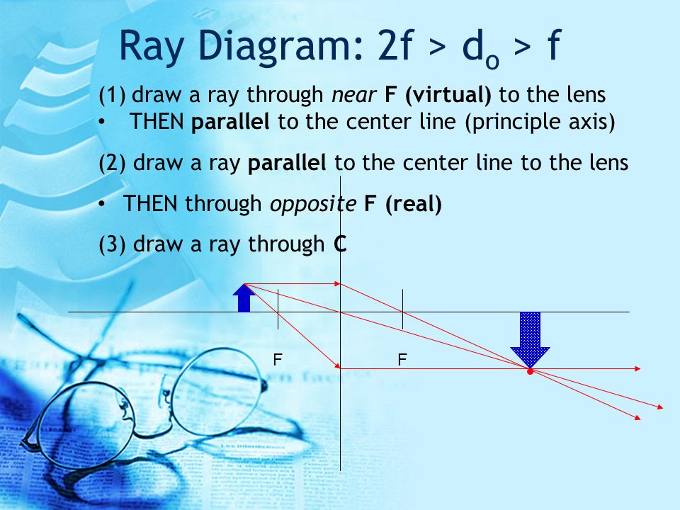
Here, Object AB is beyond 2F 1. First, we draw a ray parallel to principal axis. So, it passes through focus after refraction. We draw another ray which passes through Optical Center. So, the ray will go through without any deviation. Where both rays meet is point A'. And the image formed is A'B'. This image is formed between F 2 and 2F 2.
Draw a ray diagram of the lens system in part d.
Ray Diagrams Object N F Image Let’s check the answer by making a quick ray diagram of the situation: Ray 1: parallel then away from near focal point. Ray 2: straight through the center of the lens. Ray 3: is intended to go through far focal point but goes parallel at lens. Image is upright, diminished and virtual.
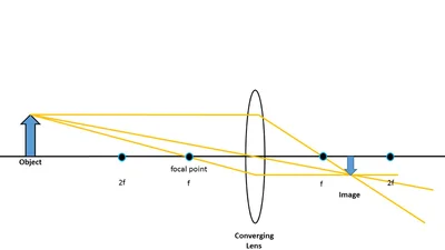
For aconvex lens, we draw the ray diagram as follows: Draw a ray from the top of the object straight through the middle of the lens. Its direction is not changed. Draw a ray from the top of the object parallel to the principal axis. It is refracted by the lens to pass through the focal point. F From the diagram we see that the image in this ...
Ray diagram for an object placed between 2F and F from a convex lens In a film or data projector, this image is formed on a screen. Film must be loaded into the projector upside down so the ...
Draw a ray diagram to show how a converging lens can form a real and enlarged image of an object. Solution: The above figure shows the image formed is real, enlarged and inverted. Question: 16. A lens forms an upright and diminished image of an object placed at its focal point. Name the lens and draw a ray diagram to show the formation of an image.










0 Response to "37 draw a ray diagram of the lens system in part d"
Post a Comment