37 arcade button wiring diagram
Led Arcade Button Wiring Diagram from cdn11.bigcommerce.com Print the electrical wiring diagram off and use highlighters to trace the signal. When you employ your finger or follow the circuit together with your eyes, it is easy to mistrace the circuit. One trick that I use is to print the same wiring diagram off twice.
The most common wiring setup for a microswitch is to have the ground wire on the very bottom prong (the common prong) and the action wire on the prong closest to the ground wire (the normally open prong). This will send a signal to the board whenever the button is pressed. This setup is used in the majority of arcade games that you will encounter.
Bass Fishing manual Club Kart wiring Diagram ClubKart-Standard manual Crazy Taxi manual F355-Deluxe manual F355-Twin manual Naomi Kit Universal Wiring Diagram Sonic & Tails Spinner Manual Transformers Owners Manual Virtual Striker 2002 Universal Kit & Service Manual. Skee Ball. Skee Ball Too Assemby & Operation Skee Ball Too! Installation ...
Arcade button wiring diagram
TAMA, The Arcade Manual Archive, strives to be the Internet's premier technical manual resource for amusement industry technology. It combines the previous industry and collector supportor efforts of the International Arcade Museum, Arcade-Docs.com, and Arcade-Manuals.com. Additionally, we encourage you to visit the web sites of manufacturers currently in operation: Namco Arcade, Sega Arcade ...
The adafruit arcade bonnet has six jst connectors for quick connect wires. Includes o ring and mounting nut. This controller will have six arcade buttons for gameplay plus start and select buttons making a total of eight arcade buttons. Diagram of how the buttons and switches are wired to the i pac for the arcadecab control panel layout.
Sanwa Joystick Wiring Diagram. There was a Sanwa JLF Wiring Guide, but I redid this one with info for wiring a I bought the 5 pin harness and joystick from focus wiringall.com on their If you use the first diagram linked, you would just need to choose picture. This time, we will install Sanwa buttons and a Sanwa joystick to our box.
Arcade button wiring diagram.
Game Manuals & Schematics. If you want the entire archive, it is available in CD format at the Online Store . M = Manual, S = Schematics, L = Parts List. P = Pinouts/wiring diagram, D = Dip switch settings. Title - Company.
Includes play instructions, illustrations of in-game characters, PCB assembly diagram, dip switch setting, test mode instructions, and wiring diagram. Part G20-00548A.Arcade Game Manual and Service Manual (part num G20-00549A) for Kiki Kai Kai, an arcade game by Taito in Japanese.
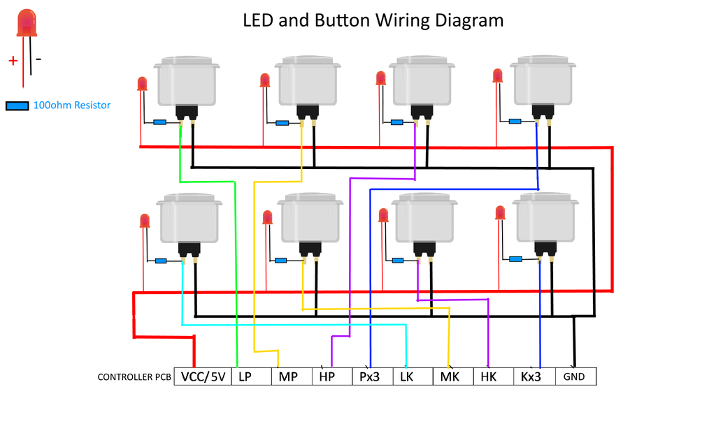
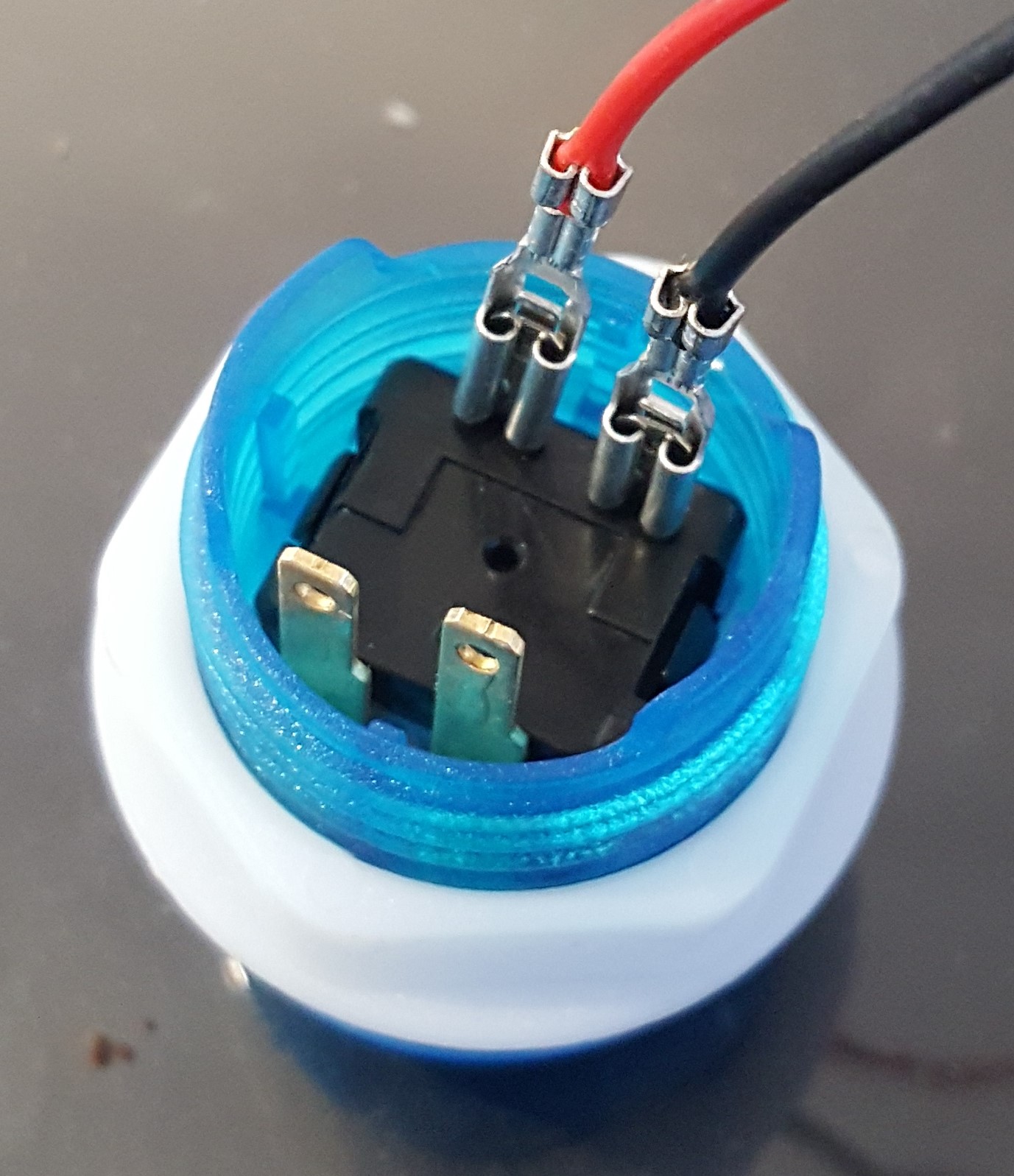
I think this diagram will work for your buttons -- related thread here. The two pin / two 0.110" Quick Disconnect wires connect to the microswitch tabs. (A and B) There should also be some "daisy-chains" for the red connectors. One daisy-chain for ground like the black wire below and one daisy-chain for 5v like the red wire below.
This page covers the arcade controls wiring instruction for The Geek Pub arcade kits. This includes wiring diagrams for the joystick, buttons, LEDs, and zero-delay encoder boards. If you do not have a Geek Pub arcade controls kit, these instructions may still be useful, as most arcade kits are fairly standard wiring.
The diagram below provides a visual reference for wiring of the components. This diagram was created using the software package Fritzing. ... Arcade Button with LED - 30mm Translucent Clear. $2.50. Add to Cart. STEMMA QT / Qwiic JST SH 4-pin Cable - 100mm Long. $0.95. Add to Cart.
Black = All black wires are ground (use a ground with each wire below) White = Mouse Button 1 (mouse 0 in MAME) - On X-Arcade = Left Pinball button Brown = Mouse Button 2 (mouse button 1 in MAME) - On X-Arcade = Right Pinball button Orange = Mouse Button 3 (mouse button 2 in MAME) - On X-Arcade = Red-lit Exit button
They're the same size as common miniature arcade controls, and require a 30mm diameter hole for mounting. Thus they are sometimes referred to as 30mm diameter. The buttons screw in place, so you can use with up to ~20mm thick material, and will cover up if the hole if it isn't perfectly round and clean.
Its possible they wired it so two button did the same function. Like a shoot on either side of the joystick. I'm seeing exposed wire on the blue/yellow where its crimped into the connector with the blue/black so its likely that is not factory. When all else fails consult the wiring diagram in the manual.
Push Button Starter Switch Wiring Diagram - push button ignition switch wiring diagram, push button start switch wiring diagram, push button starter switch wiring diagram, Every electrical arrangement consists of various distinct parts. Each component ought to be placed and linked to other parts in specific manner. Otherwise, the arrangement won't work as it ought to be.
Build a daisy chained wire harness to connect to the +5v connector on your existing board. This will power the led portion of the buttons (which by the way are the other two pins on the image you included). You will need to determine which pin on the connector is power and which ground.
Arcade Button Wiring Diagram Source: i.ytimg.com Before reading the schematic, get acquainted and understand each of the symbols. Read typically the schematic like a new roadmap.
General theory on wiring arcade switches (buttons & joysticks) Warning: This is not a terribly technical discussion. If you *really* want to understand wiring and electronics, take a look at the tutorials section on the techs & tips page, look for the electronics link. What this will attempt is a brief "how-to" on connecting up wiring to your controls.
Jamma in-1 PCB, iCade, Arcade Multigame, Multicade board, JAMMA, Jamma PCB, Jamma in-1, 60 in 1, Click Here for wiring diagrams and manuals!. I want to hook up a 60 in 1 board in it for my I see the Jamma wire harness on ebay and a power supply is that all I need or do you need a.Arcade Game Part Manuals.
New LED Arcade buttons, unboxing, how to wire and hook up, and lastly a brief review.Arcade LED MAME 2 Player USB Bundle Kit -- https://www.banggood.com/cust...
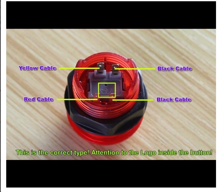
Harness: Ready made wiring or what you call your finished wiring Micro switch: Commonly used switch used for joystick and push buttons. Sometimes you will encounter micro switches with three legs instead of two. The illustration shows where you need to connect your wiring.
Arcade USB Encoder Wiring Guide. Oct 19, 2011. So you've just received your Zero Delay Arcade USB Encoder and its time to wire it up! Start by getting the USB Encoder PCB board and take note of the connections. We are going to wire up the Joystick first, so grab that and the ribbon cable. Plug one end of the ribbon cable into the joystick port ...
Step 4: Wiring the new buttons. There are two things you need to wire to get the buttons working. First is to wire the input connection which will run directly to your JPAC (or IPAC, I'll get into that in a moment). The second is to daisy-chain the power from the existing switches to power the LEDs.
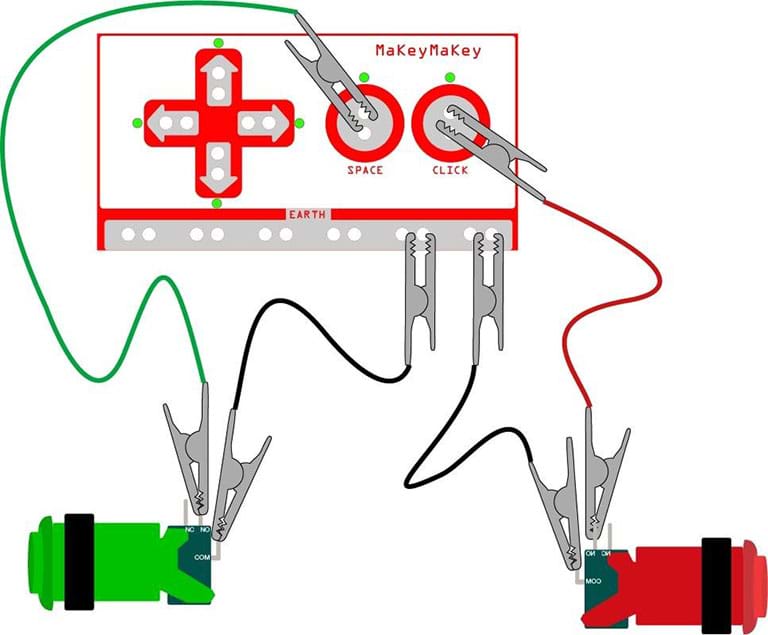
Place the arcade button through the 1" hole. Secure the arcade button by screwing the nut onto the back of the arcade button. NOTE: Screw the nut with the teeth facing the arcade button (See below) Attach the blue cables to "COM Connector 3" and "NO Connector 2" (see diagram below). Snap white plastic switch back in place.
Connecting Arcade Buttons to Raspberry Pi GPIO Pins. May 31, 2015/ Florian Maurer. The simplest and least expensive path is purchasing pre-made wires. Doing this saves you from having to crimp half the connections as well as needing to buy wire of each color by the spool. This guide covers trimming the wires to the length we need and adding a ...
Install a JAMMA Harness in an Arcade Cabinet: I have an arcade machine in a cabinet that doesn't work. I got another board, but the pins didn't match - I figured out I needed to replace the wires. I bought a JAMMA harness, but everything was in Chinese. Here's how I muddled through to …
Brown = Mouse Button 2 (mouse button 1 in MAME) Orange = Mouse Button 3 (mouse button 2 in MAME) Blue = Horizontal Disabler (use for perfect straight shots in Golf or Bowling) To install into a new wood opening, use a router to cut out 5-7/8" by 5-7/8" down to ¼". Cut 2-7/8" hole for lip/ball (the trackball housing is about 4" deep).
Circuit Diagram This provides a visual reference for wiring of the components. They aren't true to scale, just meant to be used as reference. The LEDs are embedded into the arcade button housing. They appear separate in the diagram for clarity. To power this project, we're connecting microUSB to a computer's USB port.
In this video we will walk through the different button layouts and a wiring basics overview for your arcade machine. There are several different layouts th...


0 Response to "37 arcade button wiring diagram"
Post a Comment