39 compu fire ignition wiring diagram
Step 1: Fill out pump finder above. Step 2: Add the pump to your cart. Step 3: Refer to the diagram on the product page for plumbing or refer back to this page and click the link to your fuel pump diagram. Step 4: Bulk add to cart! The following are the basic solutions to the most common systems. - For more specific variables please call tech at 913-647-7300 With the ignition switch off, remove the distributor cap and check the air gap between the Compu-Fire module and rotor. The gap should be approximately .060\". The gap must be between .030\" and .100\".IGNITION MODULE TEST - Note: Do not turn the ignition switch on during this test and leave it on.
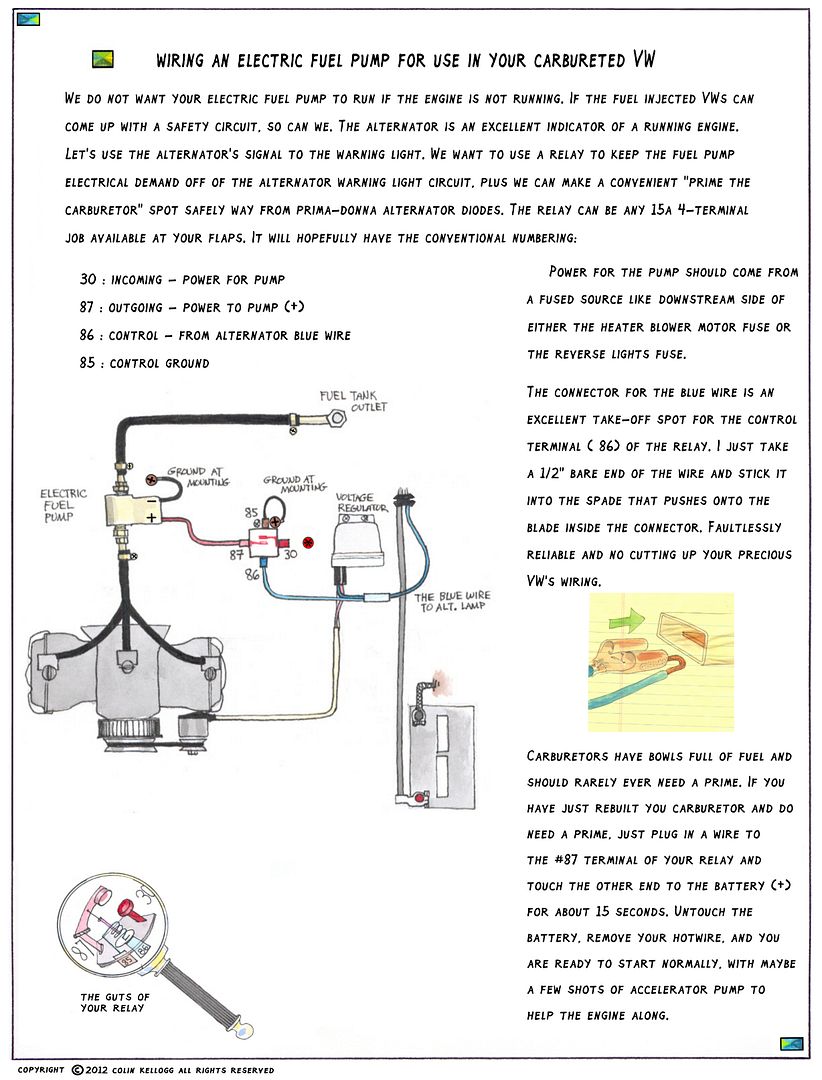
The RED wire to the CompuFire unit receives 12 volts from the ignition switch (black wire from the wiring harness). It splices into the thin red wire to the CDI unit; this wire also connects to the ignition switch. The wires to the backup lights, the automatic choke, and the idle cut-off valve also attach to this wire, as they also receive ...
Compu fire ignition wiring diagram
COMPU -FIRE® IGNITION MODULE INSTALLATION COMPU -FIRE IGNITION MODULES ARE INSTALLED WITH THE ENGINE AT T.D.C. Note: Do not use the washers Fig.#1 (5), Fig.#2 (16) or Fig. # 3 (25). 1. Clea n out the ignition cavity in the cam cover. Replace oil seal if necessary. 2. Refer to Fig.# 4. Secure Compu -Fire trigger rotor (36) with the socket head ... Compu Fire Ignition Wiring Diagram. STEP #2: INSTALL THE COMPU-FIRES ELITE 1 IGNITION COMPONENTS. NOTE: DO Carefully slit the cable jacket about one inch to expose the inner wires. CONVERTING POINTS IGNITION TO COMPU-FIREⓇ ELITE 1 IGNITION. Refer to RE-INSTALL SPARK PLUGS AND CONNECT PLUG WIRES. The ignition key rebounds to the initial position from every ignition lock position. For your safety, fasten safety belts. Page 89 Switch position 1 Ignition on Turn ignition key to position 1. Ignition is switched on. Note on operation All electrical equipment can be switched on.
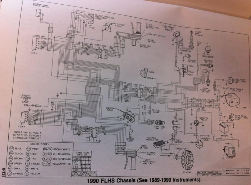
Compu fire ignition wiring diagram. The Factory Pro S36 Ignition Advance Kit advances the timing 4 degrees! Boost low and mid - use with or without a TRE. 035-inch works well for naturally-aspirated engines, if the plug wires are in good shape and the ignition is strong enough, many naturally-aspirated engines might benefit from a WIRING DIAGRAM. Nov 29, 2021 · Harley stator output voltage Compu Fire Ignition Wiring Diagram from www.vw-resource.com. To properly read a electrical wiring diagram, one offers to learn how the particular components within the method operate. For instance , when a module will be powered up also it sends out a new signal of 50 percent the voltage in addition to the technician would not know this, he'd ... Jul 08, 2014 · Fuel Pump Troubleshooting for 87-90 Mustangs Revised 11-Mar-2014 to add new fuel pump wiring diagram. Primary fuel filter: The cup filter located on the side of the motor that sits between the fuel tank and the low pressure fuel pump.
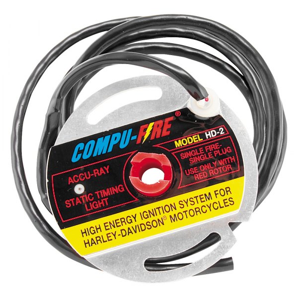
Need a spark plug wiring diagram for a 2000 europe harley soortster Your spark plug wiring shouldn't make any difference as Harley uses a dual fire ignition system. The spark plugs both fire at the same time so it doesn't make any difference which wire goes to the front or back cylinder. Wire diagram 2004 chevrolet colorado fuse 2005 ignition system wiring for chevy that has 12v during crank all diagrams 2002 canyon hummer h3 lsx part 1 switch circuit 4x4 prior 47 52 dimmer s10 which bypass lock cylinder recall passlock PLJX is a "Self Learning" unit designed to bypass all GM vehicles equipped with Passlock I, Passlock II, VATS ... CompuFire Original Ignition Module - 20100. Ignition module designed for dual-fire applications. Features built-in Accu-Ray timing light and correct dwell times. No external ignition module necessary because the module mounts entirely inside ignition housing. Rev limiter eliminated. Made in the U.S.A. NOTE: Requires the use of a mechanical ... Compu-Fire High Output Charging System for GL1500 has two and a half times more output than stock charging system! THE solution to charging problems even if the bike is LOADED with electrical accessories. 6 MB) Honda Goldwing GL1500 Radio External Wiring Diagram (157 KB) GL1800 Jan 21, 2016 · Subject: GL1500 Diaphragms The K-72 worked ...
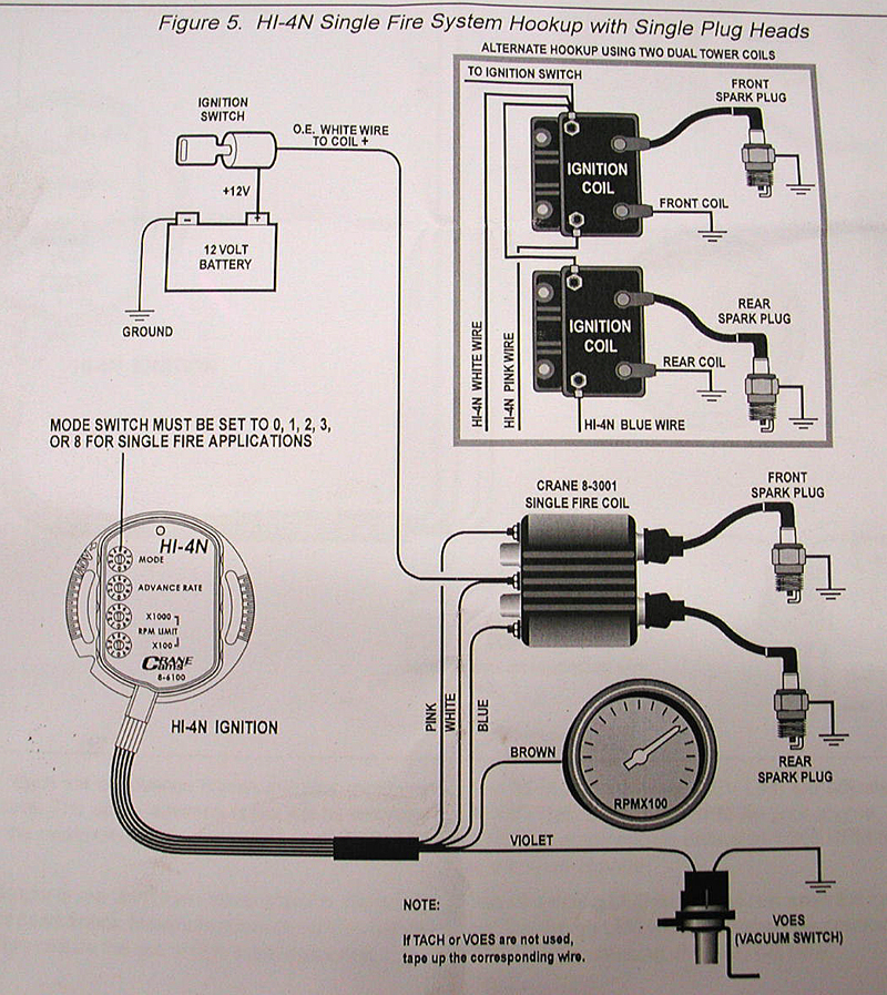
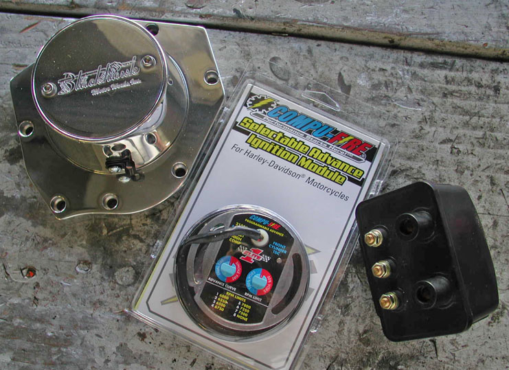
For the GC/GM Impreza WRX, the EJ20G engine had a water-cooled, Mitsubishi TD05 turbocharger; the rotational speed of the turbine ranged from approximately 20,000 rpm to 150,000 rpm and peak boost is understood to be around 11 to 12 psi. To prevent excessive boost pressure, which could cause knocking and heavier thermal loads on the pistons, the EJ20G … Bolt the COMPU-FIRE® ignition module to the frame in the stock location using the original hardware. 2. Plug the wire harness connector to the mating plug on the wiring harness. The two extra wires are for single fire applications. (see wiring hook-up) 3. See Diagram 5, 6, 6A or 6B if using adapter harness P/N 25050. Compu Fire Harley Ignition Diagram For Dummies ~ hello friends our site, this is images about compu fire harley ignition diagram for dummies posted by Ella Brouillard in Compu category on Nov 28, You can also find other images like wiring diagram, parts diagram, replacement parts, electrical diagram, repair manuals, engine diagram, engine ... Mechanical Advance Ignition Modules. The Compu-Fire mechanical advance modules are used to convert points type ignitions to electronic ignitions in 1970 and later Big Twins and Sportsters®. They may also replace the Prestolite type modules and Harley-Davidson® electronic advance modules with the addition of an OE style mechanical advance.
Your Bike's Charging System - Regulator/Rectifiers and Alternators
The ignition key rebounds to the initial position from every ignition lock position. For your safety, fasten safety belts. Page 89 Switch position 1 Ignition on Turn ignition key to position 1. Ignition is switched on. Note on operation All electrical equipment can be switched on.
32 Dyna S Ignition Wiring Diagram - Wiring Diagram List
Compu Fire Ignition Wiring Diagram. STEP #2: INSTALL THE COMPU-FIRES ELITE 1 IGNITION COMPONENTS. NOTE: DO Carefully slit the cable jacket about one inch to expose the inner wires. CONVERTING POINTS IGNITION TO COMPU-FIREⓇ ELITE 1 IGNITION. Refer to RE-INSTALL SPARK PLUGS AND CONNECT PLUG WIRES.

A Boy Blowing on a Firebrand (1621/22) // Gerrit van Honthorst Dutch, 1592-1656
COMPU -FIRE® IGNITION MODULE INSTALLATION COMPU -FIRE IGNITION MODULES ARE INSTALLED WITH THE ENGINE AT T.D.C. Note: Do not use the washers Fig.#1 (5), Fig.#2 (16) or Fig. # 3 (25). 1. Clea n out the ignition cavity in the cam cover. Replace oil seal if necessary. 2. Refer to Fig.# 4. Secure Compu -Fire trigger rotor (36) with the socket head ...
Compu Fire Ignition Wiring Diagram
Compu Fire Ignition Wiring Diagram
Crane Singlefire Zündspule durchmessen (S. 3) - Milwaukee ...
Custom Bike Twin Tec Electronic Ignition Systems - YouTube
Ultima Single Fire Ignition Wiring Diagram - Wiring Site Resource
EVO Ignition Help - Harley Davidson Forums
American Legend Motorcycles - Electronic Ignitions
Static Timing the Compu-Fire HDE-1 Ignition on my Harley Davidson Evolution Project - YouTube

Hi-4n wiring help please - Harley Davidson Forums
![[DIAGRAM] Old Fire Coil Diagram FULL Version HD Quality ...](https://s1.manualzz.com/store/data/008164740_1-9e5b623e121b2e1e93465fd707f6442e.png)
[DIAGRAM] Old Fire Coil Diagram FULL Version HD Quality ...

brown bonfire on gray field

Compu-Fire 20100 Ignition Model 20100 | MotorcycleParts2U
Compu-Fire™ | Motorcycle Ignition System Parts, Drivetrain ...
EVO Ignition Help - Harley Davidson Forums
Double Relay Article - Itinerant Air-Cooled
Compu-Fire® 20200 - Fire Mechanical Advance Ignition ...
Compu-Fire HDE-1 Ignition Static Timing… – Sportster Project

The Prairie on Fire (1827) // Alvan Fisher American, 1792–1863

flame illustration
Engine Stumble | Harley Davidson Forums

Marina City Theater, Chicago, Illinois, Roof and Partial Concrete Frame Development Drawing (1961-1962) // Bertrand Goldberg American, 1913-1997
Compu Fire Ignition Wiring Diagram

Poor Boy Conversion Wiring Diagram - Wiring Diagram

Firing Squad (1950) // Leopoldo Méndez Mexican, 1902-1969
SECTION 9 IGNITION IGNITION PARTS & ACCESSORIES INCLUDING MAGNETOS, COILS, CONTACT POINTS, CONDENSERS, TUNE UP KITS, DISTRIBUTORS, & SPARK PLUGS. - PDF Free Download
Compu-FIre Motorcycle Products | Harley Davidson Charging ...

860-880 North Lake Shore Drive, Electrical Riser Diagram (11/28/1949) // Ludwig Mies van der Rohe (American, born Germany, 1886–1969) Associate Architect: Holsman, Holsman, Klekamp and Taylor (American, 20th century) Associate Architect: Pace Associates (American, 20th century) Structural Engineer: Frank J. Kornacker (American, active 1940s–1950s)
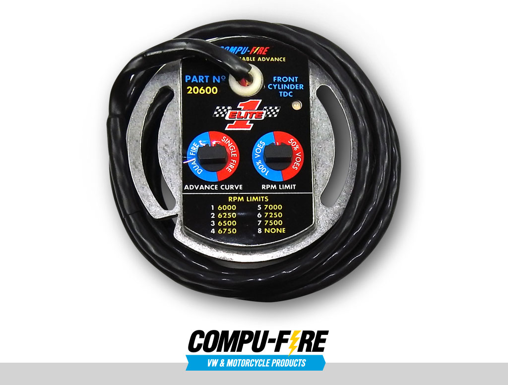
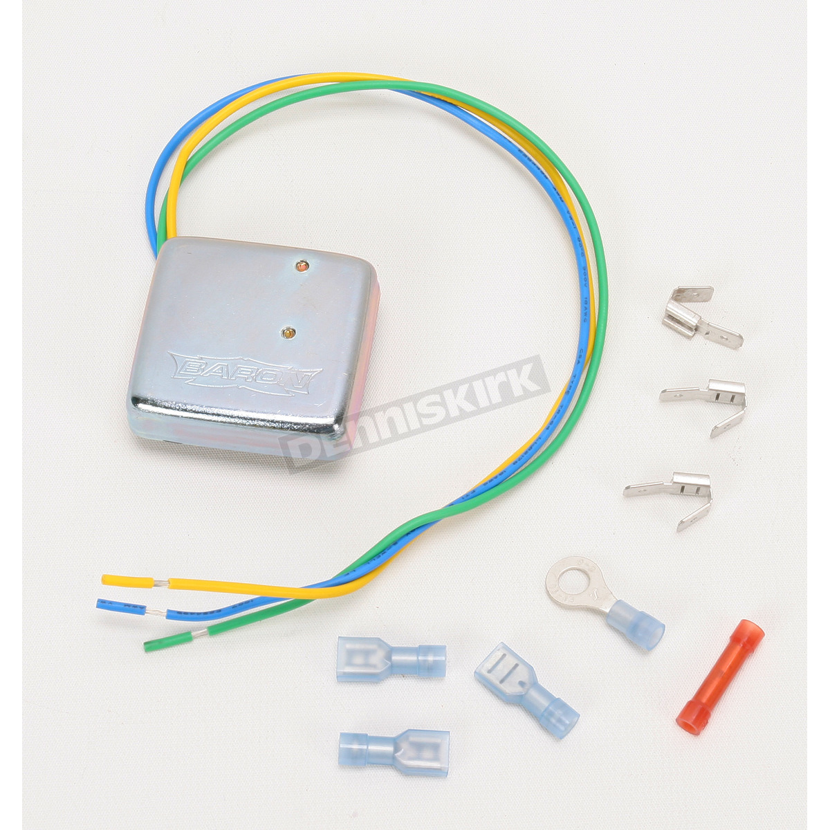
CompuFire Elite 1 Single-Fire Electronic Advance Ignition Module Kit (Non-EFI) - 20550 Harley-Davidson Motorcycle | Dennis Kirk
bonfire
How to install Compufire Ignition for VW in a 009 Distributor, by Airhead Parts - YouTube

River City I, Marina City, Chicago, Illinois, Sectional Diagram (N.d.) // Bertrand Goldberg American, 1913–1997
Compu Fire Ignition Wiring Diagram

30 Crane Hi 4 Ignition Wiring Diagram - Worksheet Cloud

Dyna 2000 Ignition Wiring Diagram - Wiring Diagram And ...

close-up photo of fire at nighttime

Club de Centre Rural: Perspective Sketch (1943) // Le Corbusier French, born Switzerland, 1887-1965
0 Response to "39 compu fire ignition wiring diagram"
Post a Comment