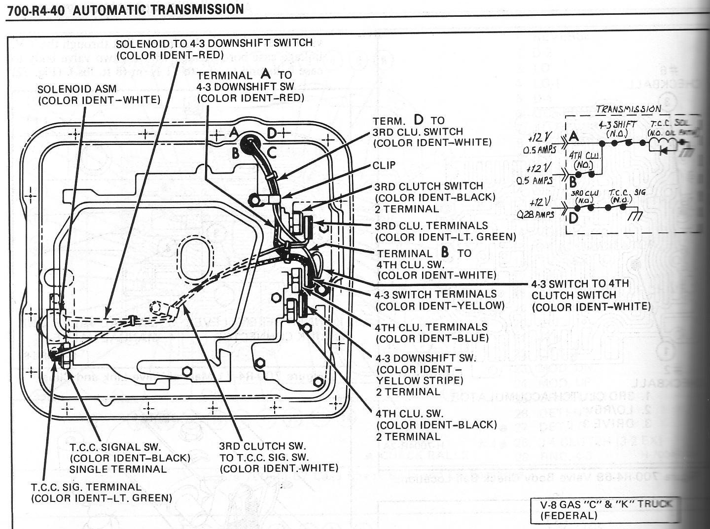
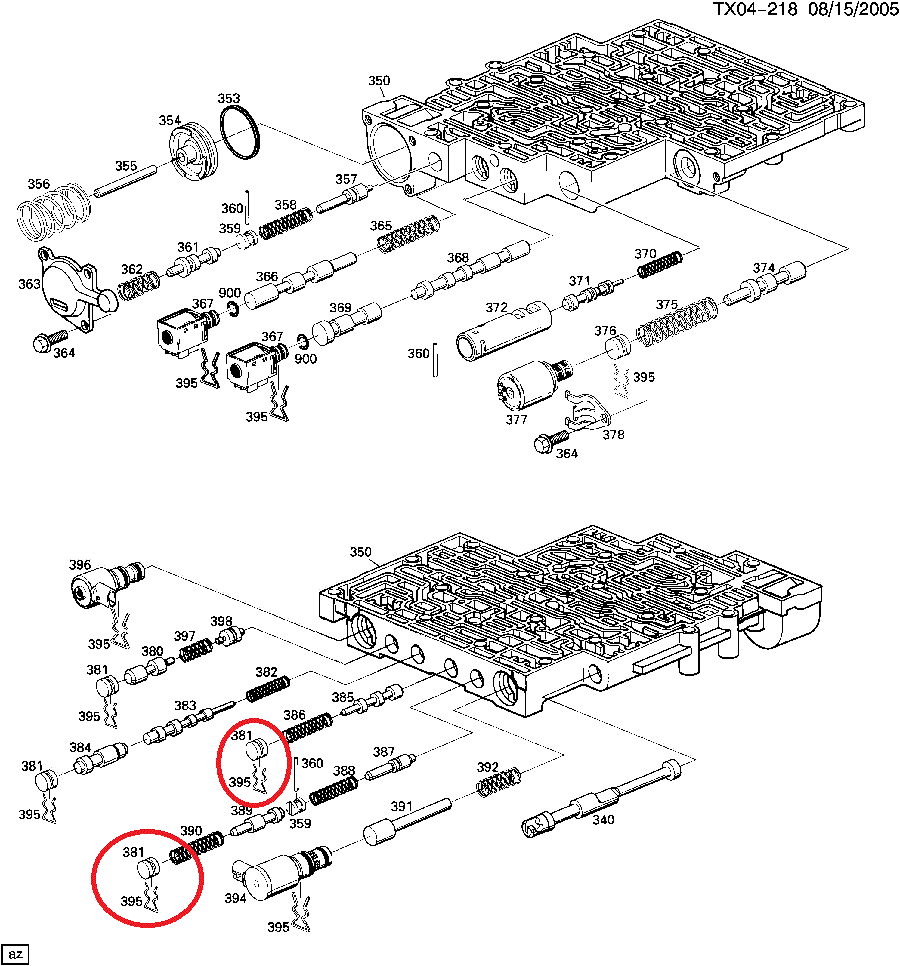
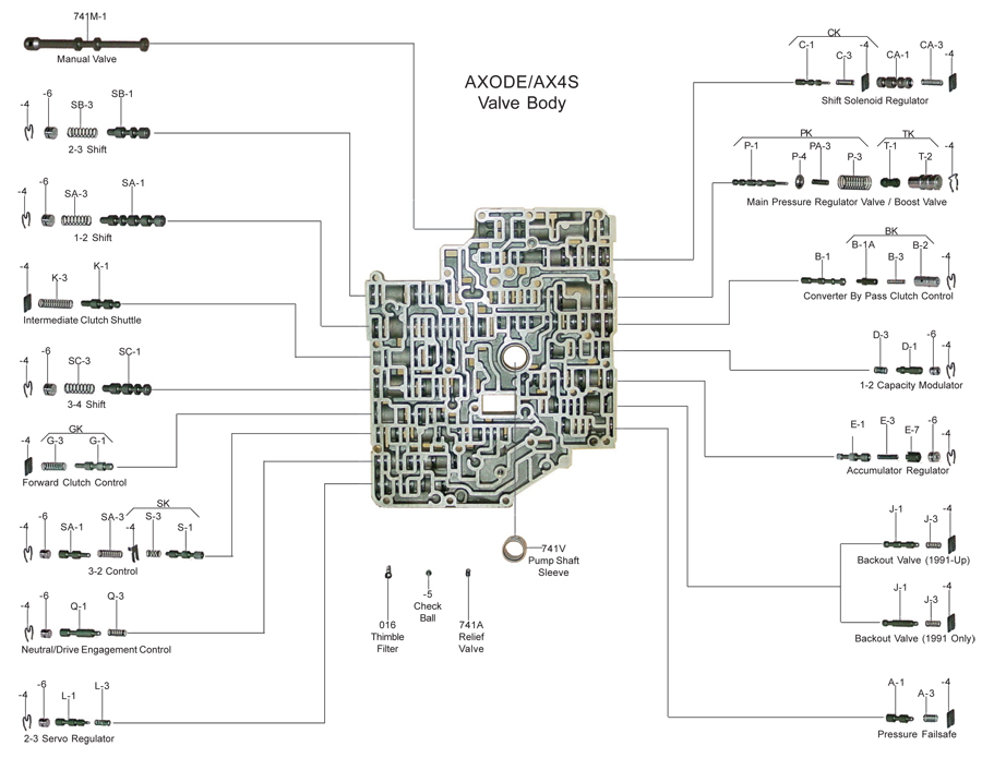
34 700r4 valve body diagram
14 Nov 2019 — Does anyone have a 700r4 valve body diagram? - Sierra 1500 GMC Cars & Trucks. Posted by bloven41 on Sep 03, 2010. Want Answer 0.I need a valve body diagram 700r4 transmission - Fixya1 answer27 Oct 2016Diagram of a completely disassembled valve body for a ...3 answers2 Sept 2019More results from www.fixya.com A transmission valve body is a major component of an automatic transmission. It's essentially a maze-like control center made up of valves, passageways, ...
the check ball placement diagrams in the instructions to determine the cor- ... valve body removal is not required (pan ... Transpak 1982-93 GM TH-700R4.14 pages

700r4 valve body diagram
Transmission repair manuals JF015E (RE0F11A) CVT7, diagrams, guides, tips and free download PDF instructions. Fluid capacity and type, valve body and solenoids charts. Hot Rod Wiring – Diagram. Please Note: This diagram was designed for 12 volt systems, but can also be used for 6 volt systems. If used for 6 volt, make all the wires heavier by 2 gauges. For example 14 gauge wire will become 12 gauge, 10 gauge will be 8 gauge, etc. Source: Mike Bishop’s book “How To Build A Traditional Ford Hot Rod ... LS Swap Components for 1967-69 Camaro/Firebird: The 1st Gen F-Body is the gold standard for muscle cars. Nothing beats the power of modernizing with a complete LS swap system. From fuel injection, manifolds and fuel pumps all the way to the exhaust system. Holley has engineered these parts to work as a system to deliver the most power and ...
700r4 valve body diagram. This listing is for a Remanufactured GM 700R4, 700-R4 Valve Body, model years 1987-1992, with Electronic Lockup. Please note that this valve body does not ... Nov 18, 2021 · The 700r4 and the 200-R4 transmission replaced the TH350 transmission in that year. The TH350 was a 3 geared transmission without the last overdrive gear. The 700r4 was a big upgrade with an additional gear (Overdrive), the 1st and 2nd gear became longer, and the transmission case itself became a bit longer. The Low Overrun Valve in the auxiliary valve body provides a smooth 2-1 Manual downshift. It also regulates the pressure applied to the Low/Reverse clutch to a ...120 pages Each layout: Displays an exploded view location guide for individual valve trains; Identifies symptoms and recommended solutions for quality rebuilds; Provides ...
The proper adjustment of the TV cable is based on the TV plunger being fully depressed with the engine at wide-open throttle (see figure 9). When the TV cable is properly adjusted the movement of the TV plunger in the valve body is calibrated to the movement of the fuel delivery system. the valve body. In most 1986 and later TH-700’s the TCC shift valve was plugged and TCC is controlled by an Elec-tronic Control Module (ECM). ALL B&M TH-700 (4L60) TRANSMISSIONS ARE BUIL T FOR ECM CONTROL OF THE TCC. If you are replacing a 1982-87 transmission with hydraulic TCC control you will have to do one of the 6 Sept 2011 · 13 posts · 4 authorsTransmissions and Drivetrain - 700r4 valve body diagram? - Any one have an exploded view of the valve body? I am going to attempt to take ...Pictures of every component of a 700R4 - ThirdGen.Org30 Jan 2017700R4 problem. Always in first gear. Dude inside with Valve ...14 Aug 2015Help!! 700R4 valve body check balls - ThirdGen.Org22 Feb 2017700R4 valve body switch functions? - ThirdGen.Org24 Apr 2010More results from www.thirdgen.org 700R4. Valve Body Interchange. Late model 700-R4 valve bodies can be exchanged if the spacer plate and checkball locations are matched to valve body.4 pages
valve body. (See Photo 4A.) Some 700R4 transmission do not have this auxiliary valve body but came with a small support plate. If you have this type of 700R4 transmission, remove the four bolts holding the small support plate to the case at the rear of the valve body. Remove the two valve body bolts holding the throttle pressure mechanism. LS Swap Components for 1967-69 Camaro/Firebird: The 1st Gen F-Body is the gold standard for muscle cars. Nothing beats the power of modernizing with a complete LS swap system. From fuel injection, manifolds and fuel pumps all the way to the exhaust system. Holley has engineered these parts to work as a system to deliver the most power and ... Hot Rod Wiring – Diagram. Please Note: This diagram was designed for 12 volt systems, but can also be used for 6 volt systems. If used for 6 volt, make all the wires heavier by 2 gauges. For example 14 gauge wire will become 12 gauge, 10 gauge will be 8 gauge, etc. Source: Mike Bishop’s book “How To Build A Traditional Ford Hot Rod ... Transmission repair manuals JF015E (RE0F11A) CVT7, diagrams, guides, tips and free download PDF instructions. Fluid capacity and type, valve body and solenoids charts.

Please donate. WebMoney: Z138632687735, R330729825060, skrill- alexfoto@bigmir.net, SWIFT - KRYVYTSKYI OLEKSANDR, BIC: PBANUA2X, IBAN: UA913052990005168745600778382, I will be glad information on the use of photos.

Please when you download the pictures tag and follow me on instagram: https://www.instagram.com/emilianovittoriosi/ you will help me to grow up! Thank you!








![[DIAGRAM] 700r4 Valve Body Wiring Diagram FULL Version HD ...](https://wiringall.com/image/4l60e-valve-body-bolt-diagram-4.jpg)

0 Response to "34 700r4 valve body diagram"
Post a Comment