37 isolation transformer wiring diagram
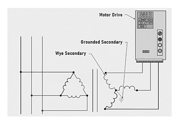
Designed for use with motor drives, the drive isolation transformer must isolate the motor from the line and handle the added loads of the drive-created harmonics. Jefferson Electric's drive isolation transformers are custom engineered for ... Drive Isolation More wiring diagrams can be found in catalog's appendix, section 15. Fusing and circuit breaker protection. How to overcurrent protect 600 Volt class transformers and associated wiring per NEC 450.3 (B), NEC 240.3 and NEC 240.6 (A). 1. Primary protection only is required if the transformer is single phase and the secondary has only two wires. Overcurrent protection rating and location are shown in Diagram A ...
The isolation transformer I selected is the 3.6 KVA IsoG2 Shoreline Isolation Transformer produced by Charles Industries in Illinois shown in Figure 1. I purchased it off the internet from iMarine. It is rated at 30 amps, 110v. While my boat was wired with two independent 30 amp circuits, one for the air
Isolation transformer wiring diagram
Isolation Transformer: Isolation transformers are used to transfer electrical power from a source of alternating current power to a device, where the powered device is isolated from the power source for safety measures. They do not have direct ground path of the current flow. They provide galvanic isolation; Galvanic isolation is a principle of isolating functional sections of electrical ... If an isolation transformer is used in such a way, it avoids the short-circuit problem, but only at the cost of “ungrounding” the oscilloscope chassis, making it unsafe to touch!!! Follow-up question: identify a way to safely use an oscilloscope to measure the shunt resistor’s voltage, without having to use an isolation transformer. Installation Warnings page 5. Installation & Operating Safety page 6. Wiring Diagrams pages 7-17. Maintenance pages 18-19. Customer Service and Warranty.21 pages
Isolation transformer wiring diagram. An isolation transformer serves a single operating room, except when supplying equipment requiring 150 V or higher (example: receptacles for laser/X-ray machines). A line isolation monitor (LIM) indicates possible leakage or fault currents from all isolated conductors to ground. • A green LED remains lit when the system is adequately isolated ... Transformer Wiring Diagram - doorbell transformer wiring diagram, furnace transformer wiring diagram, isolation transformer wiring diagram, Every electric structure is composed of various diverse parts. Each part should be placed and connected with different parts in specific way. If not, the structure won't work as it should be. Transformer Isolation Technical Articles. Isolation transformer electrical4u install transformers provide galvanic what is an and wiring 2 phase technical articles design basics of electrical circuit diagram evaluation the magic that ac line for safety purpose shielded 10 kva single airlink step up you need to boat building standards basic prosafe 200 3 installations home brew isolated data ... HBL50AITW. By Hubbell Wiring Device-Kellems. Catalog ID: HBL50AITW. Hubbell Marine Isolation Transformers, Available with or without Auto-Boost, Available in 15 kVA and 25 kVA models, White Powder Coated Steel Housing and #316 Stainless Steel. Contact Us.
3 phase isolation transformer wiring diagram - What is a Wiring Diagram? A wiring diagram is a simple visual representation with the physical connections and physical layout of your electrical system or circuit. It shows what sort of electrical wires are interconnected and may also show where fixtures and components may be attached to the system. **These radios provide differential audio output on the radio's External Speaker jack. You must use a cable with a built-in audio isolation transformer to attach this output to the SignaLink or you may damage the radio. Pin-out Pin 1 – N/C Pin 2 – N/C Pin 3 – N/C Pin 4 – Mic GND Pin 5 – Mic Pin 6 – PTT Pin 7 – GND Isolation Transformer Wiring Diagram. Assortment of isolation transformer wiring diagram. A wiring diagram is a streamlined traditional photographic representation of an electric circuit. It shows the elements of the circuit as simplified forms, and the power as well as signal links between the gadgets. A wiring diagram usually gives details about the family member… ACME ELECTRIC U MILWAUKEE, WI U 800.334.5214 U acmetransformer.com 125 GENERALGENERAL ELECTRICAL CONNECTION DIAGRAMSACME® TRANSFORMER™ WIRING DIAGRAMS PRIMARY: 240 Volts Delta SECONDARY: 208Y/120 Volts TAPS: 2, 5% BNFC X1 H1 X2 X3 H2 H3 X0 3 2 1 3 2 1 3 2 1 ConnectConnect Primary Primary Inter- Secondary
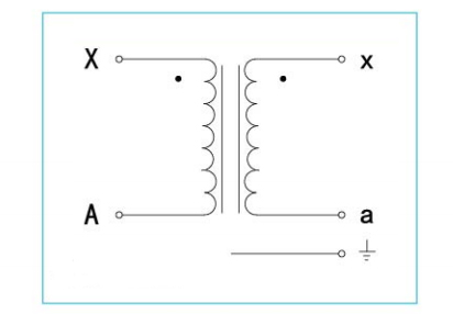
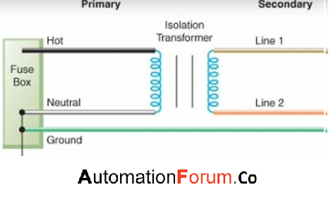
Transformer Symbols – Single Line Transformer Symbols. Following is a list of different types of transformer symbols. The single line transformer symbols list is given below at the end of the post. Single Phase Transformer Wiring Diagram. March 15, 2019. April 12, 2020. · Wiring Diagram. by Anna R. Higginbotham. single phase transformer wiring diagram - You will want a comprehensive, expert, and easy to comprehend Wiring Diagram. With this kind of an illustrative guide, you'll have the ability to troubleshoot, stop, and full your ... My company does audio visual services. When we use a single 120/208 VAC Three-phase "Y" power source for lighting, audio and video we get noise caused by the lighting dimmers injected into the audio and video. We purchased a 30 KVA Isolation transformer. We tie-in power and run it first to... Apr 07, 2017 · In the diagram above, taking an installation without an isolation transformer, the device has an earth fault (for example a live conductor has shorted to the chassis). Since Neutral and Earth are bonded in the consumer unit the system sees this as a short circuit and so a large current will flow which will blow the fuse or trip a circuit breaker.
Why Use an Isolation Transformer? – Voltage Disturbance
Assortment of 3 phase isolation transformer wiring diagram. A wiring diagram is a simplified standard photographic representation of an electric circuit. It shows the parts of the circuit as simplified forms, and the power and signal links in between the tools.
Isolation Transformer & its Application in Medical Instruments
A transformer is a passive component that transfers electrical energy from one electrical circuit to another circuit, or multiple circuits.A varying current in any coil of the transformer produces a varying magnetic flux in the transformer's core, which induces a varying electromotive force across any other coils wound around the same core.

Isolation vs Economy - TorTech Pty Ltd
Fig. 3 Step-Down Transformer used to meter High Voltage Line. In this case, a step-down isolation transformer is needed. The step-down ratio is determined by the formula: Scroll to continue with content. Ep(volts) Es(volts) = N p N s E p ( v o l t s) E s ( v o l t s) = N p N s. where, Ep is the primary voltage. Es is the secondary voltage.
On an isolation transformer, were do ground pins go ...
Wiring diagram. www.noratel.com Noratel marine isolation transformers - Type LS In order to eliminate galvanic corrosion a isolating transformer separating the shore AC power from the boats 230 Volts (or 115 volts) should be installed.

Electrical Page: 3-Phase Isolating Transformer (Delta / Star ...
3 Phase Isolation Transformer Wiring Diagram Source: electricalnotes.files.wordpress.com READ 1996 Dodge Ram 1500 Headlight Switch Wiring Diagram Database Read wiring diagrams from negative to positive plus redraw the circuit being a straight collection.

Autotransformer vs Isolation Transformer | Isolation ...
The isolation transformer is fitted with an automatic circuit breaker. This circuit breaker will switch off the isolation transformer in case of overload or short-circuit. 3.2. Temperature protection The isolation transformer is fan cooled. The fan rpm is temperature controlled. The isolation transformer will switch off in case of overheating. 3.3.

Isolation Transformers Provide Galvanic Isolation | DigiKey
Transformers are devices used to trade voltage for current in a circuit in electric power applications for uninterrupted operation. Our Low Voltage Dry Type transformers portfolio can be used in Healthcare, Data Centers, Commercial, Telecom, and Oil and Gas applications.

Isolation Transformer Circuit Diagram - BDelectricity.Com
Hubbell Marine Isolation Transformers, Available with or without Auto-Boost, Available in 15 kVA and 25 kVA models, White Powder Coated Steel Housing and #316 Stainless Steel Compare View Details
5 kVA Isolation Transformer 240V to 208V, Single Phase
The number in ( )'s following the catalog number is the electrical wiring diagram number. Page 4. 4. kVA. Primary. 460V Delta. Secondary.8 pages

Isolation Transformers Provide Galvanic Isolation | DigiKey
The Isolation Transformer completely isolates the boat from the shore ground. By connecting all metal parts to the neutral output on the secondary side of the transformer, a GFCI will trip or a fuse will blow in case of a short circuit. Soft start is a standard feature of a Victron Energy isolation transformer. It will prevent the shore power fuse

SmartGauge Electronics - Narrowboat AC systems
Buck-Boost Transformer Installation Sheet Revised on April, 2011 by T.E. If you are using this unit as an isolation transformer with a primary of 120 or 240 or 480 volts and the secondary of 12/24, 16/32, or 24/48 (depending on the model) use the wiring diagram located on the inside of the cover to the wiring compartment.
Feature Article
Select a transformer that will operate on the supply voltage available at your facility (Example: 120V, 240V, or 480V). To ensure compatibility, check the wiring diagram by clicking a part number and viewing its product page. Frequency. All the transformers in this section are rated for both 50 and 60 Hz, for use worldwide. Windings

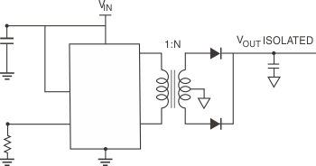
Isolated Data Transmission and Power Conversion Integrated ...
Isolation transformer you don't need an earth on the secondary side. Click to expand... If he is connecting the secondary to a N.A. service panel, the C.T. X2-X3 will automatically be earth grounded. The N.A. residential service is a 240v 1ph transformer, with a CT at 120v, this CT is taken to earth ground at the panel where it is also taken ...

DIY Isolation Transformer
The ground wire is connected to the transformer housing (if the transformer has a case, it should be connected to the ground wire of the case). Check the I/O line to make sure the wiring being accurate. First start the isolation transformer without load to observe and test whether the input and output voltages meet the requirements.

Isolation transformer - Wikipedia
BUCK-BOOST TRANSFORMER INSTALLATION SHEET 004-0921-000_0816 Buck-Boost Installation Sheet jeffersonelectric.com 1 of 4 If you are using this unit as an isolation transformer with a primary of 120 or 240 or 480 volts and the secondary of 12/24, 16/32, or 24/48 (depending on the model) use the wiring diagram located on the inside of the cover to the wiring
Basic Power Transformers
Note: This diagram does not illustrate a complete system. Refer to the appropriate ABYC text. Isolation Transformer System with Single-Phase 120-Volt Input with Grounded Secondary. Shield Grounded on Shore. Metal Case Grounded on the Boat. The green grounding wire from the shore inlet is connected to the isolation transformer shield.

Antique Radio Forums • View topic - Isolation Transformer Needed
Installation Warnings page 5. Installation & Operating Safety page 6. Wiring Diagrams pages 7-17. Maintenance pages 18-19. Customer Service and Warranty.21 pages
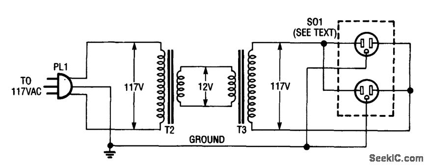
INEXPENSIVE_ISOLATION_TRANSFORMERIMPROMPTU_SETUP ...
If an isolation transformer is used in such a way, it avoids the short-circuit problem, but only at the cost of “ungrounding” the oscilloscope chassis, making it unsafe to touch!!! Follow-up question: identify a way to safely use an oscilloscope to measure the shunt resistor’s voltage, without having to use an isolation transformer.

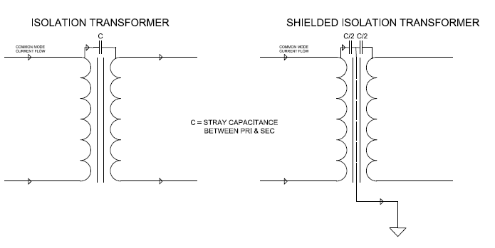
The magic that isolation transformer uses to suppress ...
Isolation Transformer: Isolation transformers are used to transfer electrical power from a source of alternating current power to a device, where the powered device is isolated from the power source for safety measures. They do not have direct ground path of the current flow. They provide galvanic isolation; Galvanic isolation is a principle of isolating functional sections of electrical ...
Isolation Transformers
what is an isolation transformer and what are its advantages ...
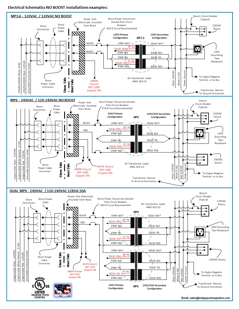
Marine Isolation Transformers | Bridgeport Magnetics
Wiring Diagram Transformer Types Isolation Transformer, PNG ...
Understanding the Design Basics of Isolation Transformers ...
ProSafe Isolation Transformer
How to Wire & Install Isolation Transformer | ATO.com

Antique Radio Forums • View topic - Stupid Question #67. I a ...
Transformer Basics Information Guide
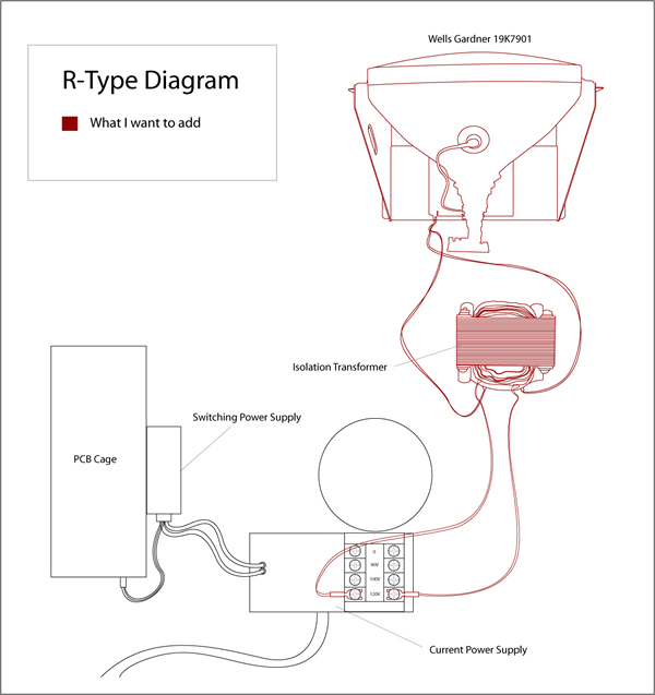
R-Type wiring diagram – Adding older monitor without ...

Victron Energy ITR050362041 Isolation Transformer 3600W with ...
Understanding and Selecting Isolation Transformers | Coilcraft
ProSafe Isolation Transformer

Line isolation monitor

Wiring 240 to 110 transformer -

Various diagram: Build a Inexpensive Isolation Transformer ...
DIY Isolation Transformer

Isolation Transformers
0 Response to "37 isolation transformer wiring diagram"
Post a Comment